Page 486 of 4323
I18
Ignition
SW
A23552
ECM
STOPSTP
ALT
BatteryE4
16 G±Y
J/C1 S14 Stop Light SW
2
G±W
BR7
Stop
Light
LH
R8
Stop
Light
RH3
5
8W±R
A W
High
Mounted
Stop Light
W±B 1L
1 1F
7
F10
Fusible
Link
BlockInstrument
Panel J/B1
4EG±Y
4B8
Brake Inhibit Relay
G±Y 4
See VSC System 2
W
J19
J/CB
C
IC
CC
C
4
BD1
1
22
1H9 H9(*1)
(*2) (*1)(*2)
BD2
12 J/C
A1
4
G±W IG2
*1: w/o Rear Spoiler
*2: w/ Rear Spoiler AM2
To Towing
Converter Relay
W±BST1±
E4 15
4C 4A1
1
3
L±B Sub J/B No.4
2
IGN1 B±O2
4D2
4A
1E 17
2 1C
1 A
J44J11
J/C J10
J
J33
J34 C
3
IJ
52C
2D 11
AM2
B W±RB±R
6
Instrument
Panel J/B
BP1
4 G±W B±O
G±W
G±W G±WSub J/B No.4
J10
J45
4
BJ J57
J/CA
W±BW±B G±W
High
Mounted
Stop LightG±WJ20
J/C G±W H
Engine Room
J/B DI±284
± DIAGNOSTICSENGINE
478 Author�: Date�:
2005 SEQUOIA (RM1146U)
WIRING DIAGRAM
Page 501 of 4323
A23548
ECM
E4
STAR ACCR
AM28
ED I18
Ignition SWB B
B±W 1C9
620
42 P
1
B±W
B 1
J2
J/C 1
17
B±O
2D
ALTE7 J38
1FGR
W4
ED2 IA1
S3 F10
Fusible
Link Block4
W±R
B±L
Battery 5B
ST 3A
1
StarterST Relay 5
B
12 3
Instrument Panel J/B
12
Engine Room J/B
2C
5 Sub J/B No. 4
P 3A 12A36
ACC CUT Relay
to Audio
J37J/C
C
GR
4 GR
N B±R
B±R
J/C BD
J51 J52B±R
STSW
E6 IG4B
Engine Room R/B No.2
2 B
2 2
2
2 2 B±RB±R RAD No.2
1C
1C
1C
1J 1J1J
1L
1E 3
5
W±L W±R
W±R
2C
2E1
3B±R
3
B1
B±W
W±B 6
A 1
2 3 58
3
J5
J/C 1
1W±B 128 B±R
W±RJ51 BE6 11
STA W±R
21
3
S2W±R4A
4B 19
9 Sub J/B No.4 GR
P1
Park/Neutral
Position SW
AM1ACC
AM2
ST2
ECU±B
SHORT PIN
B 7
B 2AM1
1
STA8
IA5
± DIAGNOSTICSENGINE
DI±299
493 Author�: Date�:
2005 SEQUOIA (RM1146U)
WIRING DIAGRAM
Page 696 of 4323
A23555
F10
Fusible
Link
Block9
+B
BatteryE1 1
8
1 E4
E6
BR 4D
B±R
67 I18 Ignition SW 2
W±R 1C 1E
1C2
13
BIG2
IA4
B±WECM
Engine Room J/B
EFI Relay
1DIGSW
MREL E4E4 17 IGN1
4E
Instrument Panel J/BSub J/B No. 4
5
AM2 Instrument Panel J/B
1
16 AM21J
2D
2F2C
2H 5
32
IA4J/C
5 4
B14 12 2
J16
A
EB EDD
J5
J/C W±B2H
2B±R
B±WB±R B±R EFI No. 1W±RB±O
B±O DI±494
± DIAGNOSTICSENGINE
688 Author�: Date�:
2005 SEQUOIA (RM1146U)
WIRING DIAGRAM
Page 698 of 4323
A21560
IGN1 Instrument
Panel J/B:
I08467
LOCKACC
ON
START
DI±496
± DIAGNOSTICSENGINE
690 Author�: Date�:
2005 SEQUOIA (RM1146U)
4 Check IGN1 fuse.
PREPARATION:
Remove the IGN1 fuse from the instrument panel J/B.
CHECK:
Check the resistance of the IGN1 fuse.
OK:
Below 1 W
NG Check for short in all harness and components
connected to IGN1 fuse.
OK
5 Check ignition switch (See page BE±24).
PREPARATION:
(a) Remove the lower finish panel.
(b) Disconnect the ignition switch connector.
CHECK:
Check resistance between terminals.
OK:
Standard:
Switch PositionTerminal ConditionSpecified Condition
LOCKAlways10 kW or more
ACC1 ± 3Below 1 W
ON1 ± 2 ± 3
5 ± 6Below 1 W
START1 ± 2
4 ± 5 ± 6Below 1 W
NG Replace ignition switch.
OK
Check and repair harness and connector be-
tween IGN fuse and ECM.
Page 764 of 4323

CAN VIM
D14151
DLC3
1314 1516 12 11 10 9 12345678 DI±562
± DIAGNOSTICSAUTOMATIC TRANSMISSION
756 Author�: Date�:
2005 SEQUOIA (RM11")
DIDIZ±01
D14150
D13872DLC3
OBD II Scan Tool
(Hand±held Tester)
CAN VIM
D14151
DLC3
1314 1516 12 11 10 9 12345678 DI±562
± DIAGNOSTICSAUTOMATIC TRANSMISSION
756 Author�: Date�:
2005 SEQUOIA (RM1146U)
DIAGNOSIS SYSTEM
DESCRIPTION
When troubleshooting On±Board Diagnostic (OBD II) vehicles,
the vehicle must be connected to the OBD II scan tool (comply-
ing with SAE J1987). Various data output from the vehicle's
ECM can then be read.
OBD II regulations require that the vehicle's on±board comput-
er illuminates the Malfunction Indicator Lamp (MIL) on the
instrument panel when the computer detects a malfunction in:
1) The emission control system/components
2) The powertrain control components (which affect vehicle
emissions)
3) The computer
In addition, the applicable Diagnostic Trouble Codes (DTCs)
prescribed by SAE J2012 are recorded in the ECM memory.
If the malfunction does not reoccur in 3 consecutive trips, the
MIL turns off automatically but the DTCs remain recorded in the
ECM memory.
To check DTCs, connect the scan tool to the Data Link Connec-
tor 3 (DLC3) of the vehicle. The scan tool displays DTCs, the
freeze frame data and a variety of the engine data.
The DTCs and freeze frame data can be erased with the scan
tool (See page DI±565).
NORMAL MODE AND CHECK MODE
The diagnosis system operates in ºnormal modeº during normal
vehicle use. In normal mode, º2±trip detection logicº is used to
ensure accurate detection of malfunctions. ºCheck modeº is
also available to technicians as an option. In check mode,
º1±trip detection logicº is used for simulating malfunction symp-
toms and increasing the system's ability to detect malfunctions,
including intermittent malfunctions.
2±TRIP DETECTION LOGIC
When a malfunction is first detected, the malfunction is tempo-
rarily stored in the ECM memory (1st trip). If the ignition switch
is turned OFF and then ON again, and the same malfunction is
detected again, the MIL will illuminate.
Page 898 of 4323
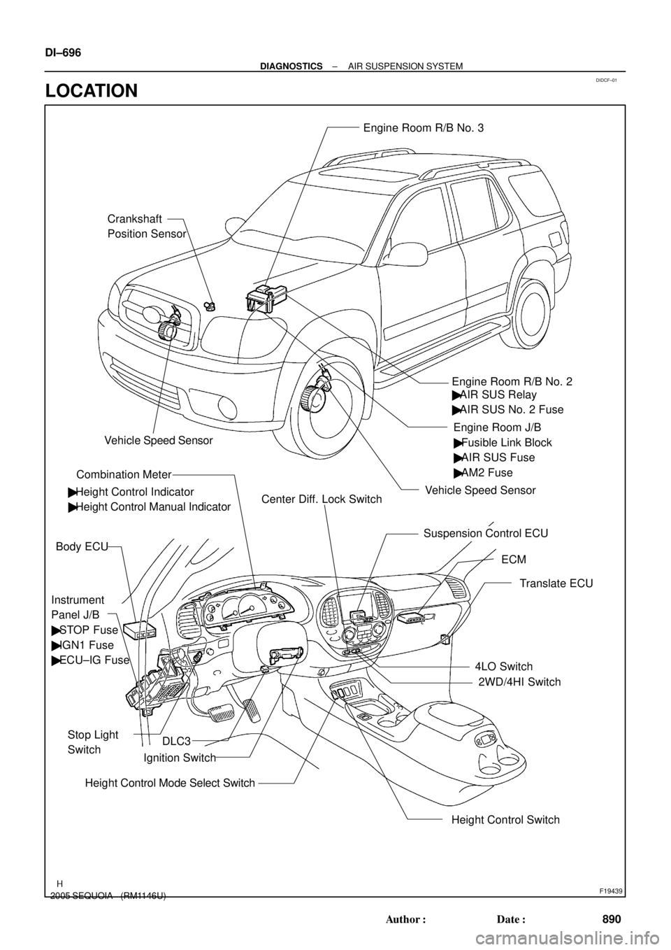
DIDCF±01
F19439
Crankshaft
Position SensorEngine Room R/B No. 3
Engine Room J/B
Instrument
Panel J/B
� STOP Fuse
� IGN1 Fuse
� ECU±IG Fuse
Stop Light
Switch
Combination Meter
Height Control Switch Body ECU
ECM Engine Room R/B No. 2
Suspension Control ECU
Translate ECU
4LO Switch
2WD/4HI Switch
Height Control Mode Select SwitchIgnition Switch � Height Control Indicator� Fusible Link Block
� AIR SUS Fuse
� AM2 Fuse
� Height Control Manual IndicatorCenter Diff. Lock Switch
DLC3
Vehicle Speed Sensor
Vehicle Speed Sensor
� AIR SUS Relay
� AIR SUS No. 2 Fuse DI±696
± DIAGNOSTICSAIR SUSPENSION SYSTEM
890 Author�: Date�:
2005 SEQUOIA (RM1146U)
LOCATION
Page 950 of 4323
F19443
Height Control
Compressor
H131
Engine Room R/B No. 2
G±Y AIR SUS Relay
Battery J28
J/C W
BM21
IC48
IA121
WWW
2
22
2 3
25
1W
9B
5
W±B
J8
J/C
AAW±B
1K12
1F9
A W±B
IESuspension
Control
ECU
IA125
G±Y
S255
RC F10
Fusible Link Block
ALT
Instrument
Panel J/BAIR SUS DI±748
± DIAGNOSTICSAIR SUSPENSION SYSTEM
942 Author�: Date�:
2005 SEQUOIA (RM1146U)
WIRING DIAGRAM
Page 955 of 4323
F19444
Height Control Compressor
(Compressor/Height Control Dryer)
H133
Engine Room R/B No. 2
W±B
Battery J28
J/CR±L
BM23
IN115
S2520
2
3
25
1W
9B
5
J8
J/C
AAW±B
1K12
1F9
A W±B
IESuspension
Control
ECU
RC F10
Fusible Link Block
AIR SUS
Instrument
Panel J/BRM+ R±L R±L
H134
BR±Y
BM24
IA121S2521
BR±Y BR±Y
RM±
AIR SUS Relay H131
W
BM21
IC48
WW W
22
2 S255
G±Y IN16
IA125
G±Y
BJ H132
BM22
W±B
AJ19
J/C W±BALT
± DIAGNOSTICSAIR SUSPENSION SYSTEM
DI±753
947 Author�: Date�:
2005 SEQUOIA (RM1146U)
WIRING DIAGRAM


H133
Engine Room R/B No. 2
W±B
Battery J28
J/CR±L
BM23
IN115
S2520
2
3
25
1W
9B
5
J8
J/C
AAW±B
1K12
1F9
A W±B
IESuspension
Contro")