Page 184 of 4323

BRAKE
SERVICE DATA
Brake pedal height (from dash panel)151.1 ± 165.1 mm (5.949 ± 6.500 in.)
Brake pedal f")
SS084±03
SS±42
± SERVICE SPECIFICATIONSBRAKE
184 Author�: Date�:
2005 SEQUOIA (RM1146U)
BRAKE
SERVICE DATA
Brake pedal height (from dash panel)151.1 ± 165.1 mm (5.949 ± 6.500 in.)
Brake pedal free play1 ± 6 mm (0.04 ± 0.24 in.)
Brake pedal reserve distance at 490 N (590 kgf, 110.2 lbf)More than 95 mm (3.74 in.)
Front brake pad thickness STD11.5 mm (0.453 in.)
Minimum1.0 mm (0.039 in.)
Front brake disc thickness STD28.0 mm (1.102 in.)
Minimum26.0 mm (1.024 in.)
Front brake disc runout Maximum0.07 mm (0.0028 in.)
Rear brake pad thickness STD10 mm (0.39 in.)
Minimum1.0 mm (0.039 in.)
Rear brake disc thickness STD18.0 mm (0.709 in.)
Minimum16.0 mm (0.611 in.)
Rear brake disc runout Maximum0.1 mm (0.0039 in.)
Rear brake disc inside diameter STD210.0 mm (8.27 in.)
Maximum211.0 mm (8.31 in.)
Rear brake shoe lining thickness for rear disc brake STD4.0 mm (0.157 in.)
Minimum1.0 mm (0.039 in.)
Parking brake clearance between rear shoe and lever0.25 mm (0.010 in.)
Parking brake pedal travel at 300 N (31 kgf, 67 lbf)6 ± 9 clicks
Stop light switch clearance0.5 ± 2.4 mm (0.020 ± 0.095 in.)
Parking brake adjusting shim thickness for rear disc brake
0.3 mm (0.012 in.)
0.4 mm (0.016 in.)
0.5 mm (0.020 in.)
0.6 mm (0.024 in.)
0.9 mm (0.035 in.)
Page 186 of 4323

STEERING
SERVICE DATA
POWER STEERING FLUID
Oil level rise Maximum5 mm (0.20 in.)
Oil pressure at")
SS08W±04
SS±44
± SERVICE SPECIFICATIONSSTEERING
186 Author�: Date�:
2005 SEQUOIA (RM1146U)
STEERING
SERVICE DATA
POWER STEERING FLUID
Oil level rise Maximum5 mm (0.20 in.)
Oil pressure at idle speed with valve closed Minimum8,336 kPa (85 kgf/cm2, 1,209 psi)
STEERING WHEEL
Steering wheel freeplayMaximum30 mm (1.18 in.)
Steering effort at idle speedReference:4.9 N´m (50 kgf´cm, 43 in.´lbf)
PS VANE PUMP
Pump shaft and front housing bushing oil clearance STD0.03±0.05 mm (0.0012±0.0020 in.)
Pump shaft and front housing bushing oil clearanceMaximum0.07 mm (0.0028 in.)
Vane plate heightMinimum8.6 mm (0.339 in.)
Vane plate thickness Minimum1.397 mm (0.0550 in.)
Vane plate lengthMinimum14.991 mm (0.5902 in.)
Vane plate and pump rotor groove clearanceMaximum0.033 mm (0.0013 in.)
Vane plate length Pump rotor and cam ring mark
None14.999±15.001 mm (0.59051±0.59059 in.)
114.997±14.999 mm (0.59043±0.59051 in.)
214.995±14.997 mm (0.59035±0.59043 in.)
314.993±14.995 mm (0.59027±0.59035 in.)
414.991±14.993 mm (0.59020±0.59027 in.)
Flow control valve spring length Minimum33.2 mm (1.307 in.)
Pump rotating torqueMaximum0.28 N´m (2.8 kgf´cm, 2.4 in.´lbf) or less
PS GEAR
Steering rack runout Maximum0.03 mm (0.0118 in.)
Total preload Turning1.2±1.6 N´m (12±16 kgf´cm, 10.4±13.9 in.´lbf)
Page 726 of 4323

BASIC INSPECTION
1. CHECK FLUID LEVEL
(a) Using")
DIDIP±01
12345678
9 10111213141516
D13649
DLC3:
CG
TC
D13654
DI±524
± DIAGNOSTICSAUTOMATIC TRANSMISSION
718 Author�: Date�:
2005 SEQUOIA (RM1146U)
BASIC INSPECTION
1. CHECK FLUID LEVEL
(a) Using SST, create a short±circuit between terminals TC
and CG of the DLC3.
SST 09843±18040
(b) Start the engine and run at idle.
�The A/C switch must be turned off.
�On models with active height control suspension &
adaptive variable suspension, turn the height con-
trol switch off.
(c) Slowly move the shift lever through all positions from P to
L, and move it back to the P position.
(d) Switch to the fluid temperature detection mode.
Move the shift lever from the N to the D position, or from
D to N, within 1.5 seconds. (Repeat this operation for 6 se-
conds or more.)
OK: The A/T OIL TEMP warning light comes on for 2
seconds and then goes off.
(e) Return the shift lever to the P position and disconnect ter-
minals TC and CG.
(f) Idle the engine to raise oil temperature.
(g) Lift up the vehicle immediately after the meter indicator
light (ATF temperature warning light) comes on.
�The A/T OIL TEMP warning light indicates the ATF
temperature according to the following table.
ATF Temp.Less than optimized
temperatureOptimized temperatureMore than optimized
temperature
A/T OIL TEMP warning lightOFFONBlinking
Page 731 of 4323

(4) Temporarily install th")
D14139Overflow Plug
D14140
Refill Plug
12345678
9 10111213141516
D13649
DLC3:
CG
TC
± DIAGNOSTICSAUTOMATIC TRANSMISSION
DI±529
723 Author�: Date�:
2005 SEQUOIA (RM1146U)
(4) Temporarily install the gasket and overflow plug.
Torque: 20 NVm (204 kgfVcm, 15 ftVlbf)
(5) Add the proper amount of ATF through the refill
hole.
NOTICE:
Refill amount differs depending on the related procedures
indicated below.
Related proceduresRefill amount
Removal and installation of oil pan1.7 liters (1.8 us qts, 1.5 lmp.qts)
Removal of transmission valve body
assy4.3 liters (4.5 us qts, 3.8 lmp.qts)
Removal of torque converter assy5.4 liters (5.7 us qts, 4.8 lmp.qts)
(6) Temporarily install the O±ring and refill plug.
Torque: 39 NVm (400 kgfVcm, 29 ftVlbf)
(7) Lower down the vehicle.
(8) Using SST, create a short±circuit between terminals
TC and CG of the DLC3.
SST 09843±18040
(9) Start the engine and run at idle.
NOTICE:
�The A/C switch must be turned off.
�On models with active height control suspension &
adaptive variable suspension, turn the height control
switch off.
(10) Slowly move the shift lever from the P to the 2±L
position.
Return the shift lever to the P position.
Page 897 of 4323
DIDCB±01
± DIAGNOSTICSAIR SUSPENSION SYSTEM
DI±695
889 Author�: Date�:
2005 SEQUOIA (RM1146U)
AIR SUSPENSION SYSTEM
PRECAUTION
Be sure to switch the height control mode select switch to manual mode and cancel the auto leveling
function when:
�Jacking up the vehicle.
�A trailer etc. is attached to the vehicle.
NOTICE:
When disconnecting the battery terminal, initialize the following system after the terminal is recon-
nected.
System NameSee Page
Back Door Power Window Control SystemBE±77
Page 898 of 4323
DIDCF±01
F19439
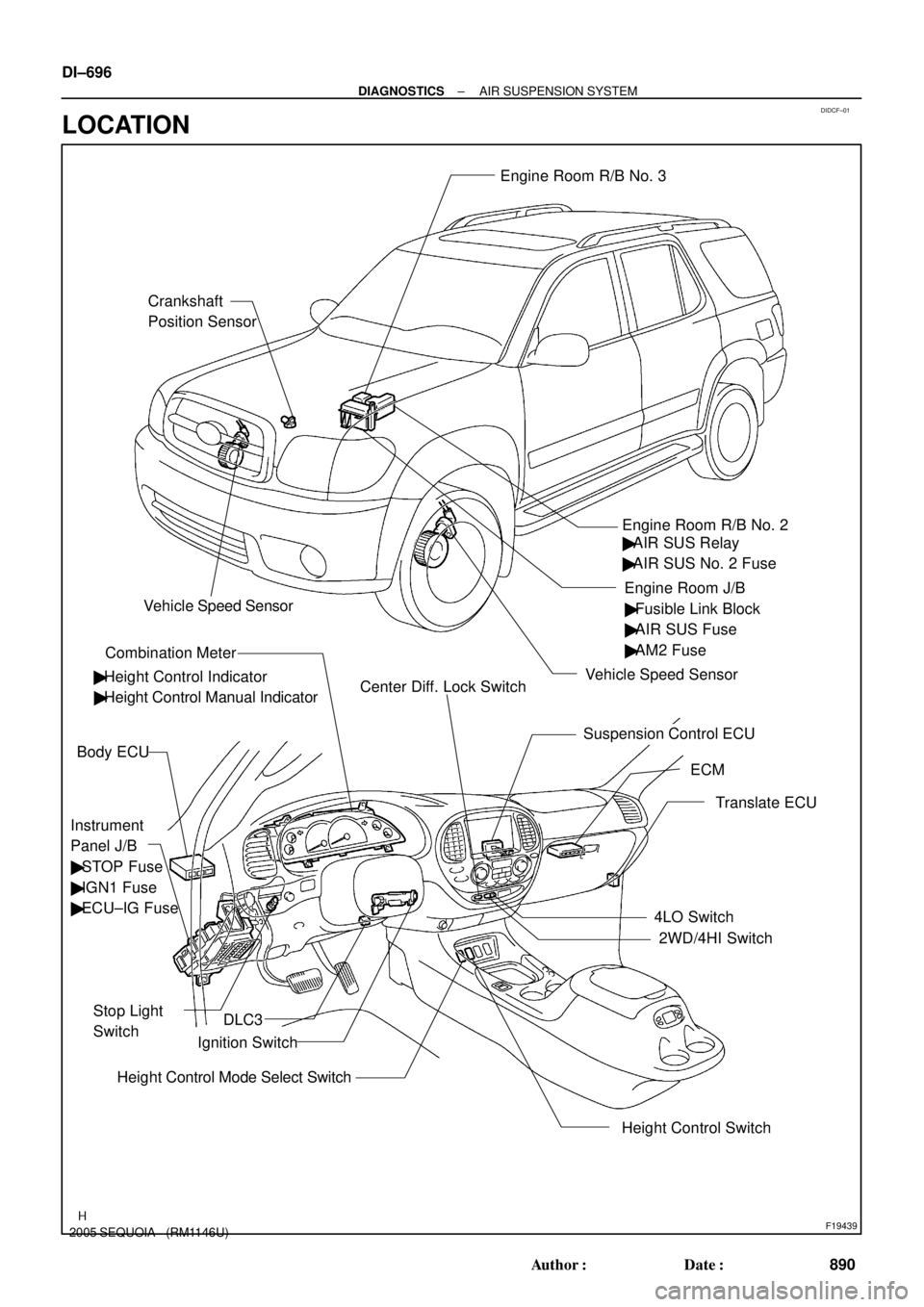
Crankshaft
Position SensorEngine Room R/B No. 3
Engine Room J/B
Instrument
Panel J/B
� STOP Fuse
� IGN1 Fuse
� ECU±IG Fuse
Stop Light
Switch
Combination Meter
Height Control Switch Body ECU
ECM Engine Room R/B No. 2
Suspension Control ECU
Translate ECU
4LO Switch
2WD/4HI Switch
Height Control Mode Select SwitchIgnition Switch � Height Control Indicator� Fusible Link Block
� AIR SUS Fuse
� AM2 Fuse
� Height Control Manual IndicatorCenter Diff. Lock Switch
DLC3
Vehicle Speed Sensor
Vehicle Speed Sensor
� AIR SUS Relay
� AIR SUS No. 2 Fuse DI±696
± DIAGNOSTICSAIR SUSPENSION SYSTEM
890 Author�: Date�:
2005 SEQUOIA (RM1146U)
LOCATION
Page 899 of 4323
F19440
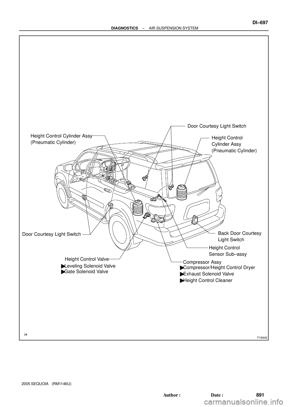
Height Control
Cylinder Assy
(Pneumatic Cylinder)
Height Control Valve Height Control Cylinder Assy
(Pneumatic Cylinder)
Door Courtesy Light Switch
� Leveling Solenoid Valve
� Gate Solenoid ValveDoor Courtesy Light Switch
� Compressor/Height Control Dryer
� Exhaust Solenoid Valve
� Height Control Cleaner
Height Control
Sensor Sub±assy
Compressor Assy
Back Door Courtesy
Light Switch
± DIAGNOSTICSAIR SUSPENSION SYSTEM
DI±697
891 Author�: Date�:
2005 SEQUOIA (RM1146U)
Page 900 of 4323
DIDCI±01
F19438
Height Control Sensor
Sub±assy
Height Control Mode
Select Switch
Body ECU
Stop Light Switch
Front Door Courtesy
Light Switch (Driver)
Front Door Courtesy
Light Switch
(Passenger)
Rear Door Courtesy
Light Switch (LH)
Rear Door Courtesy
Light Switch (RH)
Back Door Courtesy
Light SwitchCombination Meter
Leveling Solenoid Valve
AIR SUS Relay
DLC3
ECM
Translate ECU Compressor/
Height Control Dryer
Exhaust Solenoid Valve Height Control Valve
Compressor Assy Gate Solenoid Valve IG
BBAT
SBL2
SHRL
SGL2VN
HI
NR
LO
TD
UPSW
DWSW
Door
STPSLRR
SLRL
RC
RM+
RM±
SLEX
SIL
CANH
CANL
CANSuspension
Control ECU Height Control Switch
GND From IG SwitchFrom Battery
From
Battery DI±698
± DIAGNOSTICSAIR SUSPENSION SYSTEM
892 Author�: Date�:
2005 SEQUOIA (RM1146U)
SYSTEM DIAGRAM


Front Door Courtesy
Light Switch
(Passenger)")