Page 2613 of 4323

15. SET TIMING BELT TENSIO")
P20636
1.27 mm
Hexagon Wrench
A04454
1.27 mm
Hexagon Wrench
A23307Turn
A23308
A23306
SST
EM±26
± ENGINE MECHANICALTIMING BELT
2605 Author�: Date�:
2005 SEQUOIA (RM1146U)
15. SET TIMING BELT TENSIONER
(a) Using a press, slowly press in the push rod using 981 ±
9,807 N (100 ± 1,000 kgf, 220 ± 2,205 lbf) of pressure.
(b) Align the holes of the push rod and housing, and pass a
1.27 mm hexagon wrench through the holes to keep the
setting position of the push rod.
(c) Remove the belt tensioner from the press.
(d) Install the dust boot to the belt tensioner.
16. INSTALL TIMING BELT TENSIONER
(a) Temporarily install the belt tensioner with the 2 bolts.
(b) Alternately tighten the 2 bolts.
Torque: 26 N´m (270 kgf´cm, 19 ft´lbf)
(c) Using pliers, remove the 1.27 mm hexagon wrench from
the belt tensioner.
17. CHECK VALVE TIMING
(a) Temporarily install the crankshaft pulley bolt.
(b) Slowly turn the crankshaft pulley 2 revolutions from the
TDC to TDC.
NOTICE:
Always turn the crankshaft pulley clockwise.
(c) Check that each pulley aligns with the timing marks as
shown in the illustration.
If the timing marks do not align, remove the timing belt and rein-
stall it.
18. TIGHTEN CRANKSHAFT PULLEY BOLT
Using SST, install the pulley bolt.
SST 09213±70011 (90119±08216), 09330±00021
Torque: 245 N´m (2,500 kgf´cm, 181 ft´lbf)
Page 2618 of 4323
A23302
RH No.3 Timing Belt Cover
No.2 Timing
Belt Cover
LH No.3 Timing Belt Cover Drive Belt Idler Pulley
Camshaft Position
Sensor ConnectorCover Plate
Oil Cooler Pipe Engine Wire
7.5 (76, 66 in.´lbf)
16 (160, 12)
7.5 (76, 66 in.´lbf)
N´m (kgf´cm, ft´lbf) : Specified torque
Wire Grommet
39 (400, 29)
A23373
Timing BeltRH Camshaft Timing Pulley
LH Camshaft Timing Pulley
Timing Belt Tensioner
Fan BracketDust Boot
16 (160, 12)
32 (330, 24)
26 (270, 19)
N´m (kgf´cm, ft´lbf) : Specified torque
8.1 (83, 72 in.´lbf)
± ENGINE MECHANICALCYLINDER HEAD
EM±31
2610 Author�: Date�:
2005 SEQUOIA (RM1146U)
Page 2828 of 4323
B17476
RH No.3 Timing Belt Cover
LH No.3 Timing Belt CoverNo.2 Timing Belt Cover
Camshaft Position
Sensor Connector
Engine Wire
Oil Cooler Pipe
Timing Belt
Fan Bracket Drive Belt Timing Pulley
Timing Belt Tensioner Dust Boot
N´m (kgf´cm, ft´lbf) : Specified torque Cover Plate
39 (400,29)
32 (330, 24)
16 (160, 12)
Water Bypass
Hose
Grommet
16 (160, 12)
245 (2,500, 181)
CO±4
± COOLINGWATER PUMP
2820 Author�: Date�:
2005 SEQUOIA (RM1146U)
Page 2846 of 4323
LU08P±10
B17476
RH No.3 Timing Belt Cover
LH No.3 Timing Belt CoverNo.2 Timing Belt Cover
Camshaft Position
Sensor Connector
Engine Wire
Drive Belt Idler PulleyTiming Belt
Fan Bracket
N´m (kgf´cm, ft´lbf) : Specified torqueOil Cooler Pipe
Timing Belt Tensioner Dust Boot
Cover Plate
32 (330, 24)
Water Bypass
Hose
Grommet
245 (2,500, 181)
39 (400,29)
16 (160, 12)
16 (160, 12)
LU±4
± LUBRICATIONOIL PUMP
2838 Author�: Date�:
2005 SEQUOIA (RM1146U)
OIL PUMP
COMPONENTS
Page 3013 of 4323

5. INSPECT TOE±IN
Toe±in (to")
SA3213
AB
Front
C D
R13228
R13229
FA0018
AB
FrontA
B
A: Inside
B: Outside
± SUSPENSION AND AXLEFRONT WHEEL ALIGNMENT
SA±9
3005 Author�: Date�:
2005 SEQUOIA (RM1146U)
5. INSPECT TOE±IN
Toe±in (total):
UCK35L±GKBSKA
Tire size: P245/70R16
Tire size: P265/70R16 and P265/65R17
Tire size: P265/65R17 (*1)
UCK35L±GKBLKA
UCK45L±GKBSKA
Tire size: P265/70R16 (*1)
UCK45L±GKBLKA
A + B: 0°05' ± 0°09' (0.09° ± 0.15°)
C ± D: 1.19 ± 2 mm (0.05 ± 0.08 in.)
A + B: 0°05' ± 0°09' (0.09° ± 0.15°)
C ± D: 1.29 ± 2 mm (0.05 ± 0.08 in.)
A + B: 0°05' ± 0°09' (0.09° ± 0.15°)
C ± D: 1.28 ± 2 mm (0.05 ± 0.08 in.)
A + B: 0°05' ± 0°09' (0.08° ± 0.15°)
C ± D: 1.15 ± 2 mm (0.05 ± 0.08 in.)
A + B: 0°05' ± 0°09' (0.08° ± 0.15°)
C ± D: 1.08 ± 2 mm (0.04 ± 0.08 in.)
A + B: 0°05' ± 0°09' (0.08° ± 0.15°)
C ± D: 1.07 ± 2 mm (0.04 ± 0.08 in.)
A + B: 0°04' ± 0°09' (0.07° ± 0.15°)
C ± D: 0.99 ± 2 mm (0.04 ± 0.08 in.)
(*1): Air suspension models only
If the toe±in is not within the specified values, adjust the rack
ends.
6. ADJUST TOE±IN AND WHEEL ANGLE
(a) Remove the 2 clips.
(b) Loosen the tie rod end lock nuts.
(c) Turn the right and left rack ends by an equal amount to
adjust the toe±in.
HINT:
Try to adjust the toe±in to the center of the specified values.
(d) Make sure that the lengths of the right and left rack ends
are the same.
Rack end length difference: 1.5 mm (0.059 in.) or less
(e) Tighten the tie rod end lock nuts.
Torque: 55 N´m (560 kgf´cm, 41 ft´lbf)
(f) Place the boots on the seats and install the clips.
HINT:
Make sure that the boots are not twisted.
(g) Inspect the wheel angle.
Turn the steering wheel fully and measure the turning
angle.
Page 3027 of 4323
R13196
SST
± SUSPENSION AND AXLEFRONT AXLE HUB
SA±23
3019 Author�: Date�:
2005 SEQUOIA (RM1146U)
(b) Using SST, disconnect the steering knuckle.
SST 09950±40011 (09951±04010, 09952±04010,
09553±04020, 09554±04010, 09955±04031,
09958±04011)
(c) Remove the nut and steering knuckle.
NOTICE:
4WD:
Be careful not to damage the oil seal and drive shaft boot.
HINT:
4WD:
When it is difficult to disconnect the drive shaft, tap the tip of the
drive shaft with a plastic hammer.
Page 3032 of 4323

INSTALLATION
1. INSTALL STEERING KNUCKLE
(a) 4WD:
Insert the drive shaft into the axle hub and temp")
SA23J±05
SA±28
± SUSPENSION AND AXLEFRONT AXLE HUB
3024 Author�: Date�:
2005 SEQUOIA (RM1146U)
INSTALLATION
1. INSTALL STEERING KNUCKLE
(a) 4WD:
Insert the drive shaft into the axle hub and temporarily tighten the nut.
NOTICE:
Be careful not to damage the oil seal and drive shaft boot.
(b) Connect the steering knuckle to the upper suspension arm.
(c) Install the nut and a new cotter pin.
If the holes for the cotter pin are not aligned, tighten the nut further up to 60°.
Torque: 105 N´m (1,100 kgf´cm, 77 ft´lbf)
2. CONNECT LOWER BALL JOINT
Connect the lower ball joint to the steering knuckle with the 4 bolts.
Torque: 65 N´m (663 kgf´cm, 48 ft´lbf)
3. INSTALL SHOCK ABSORBER (See page SA±70)
4. INSTALL BRAKE CALIPER
(a) Install the disc, brake caliper and 2 bolts.
Torque: 123 N´m (1,250 kgf´cm, 90 ft´lbf)
(b) Install the brake line clamp to the steering knuckle with the bolt.
Torque: 28 N´m (285 kgf´cm, 21 ft´lbf)
5. CONNECT SPEED SENSOR AND WIRE HARNESS CLAMP
Connect the speed sensor and wire harness clamp to the steering knuckle with the 2 bolts.
Torque: 8.0 N´m (82 kgf´cm, 71 ft´lbf)
6. 4WD:
INSTALL DRIVE SHAFT LOCK NUT
(a) While applying the brakes, tighten the nut.
Torque: 235 N´m (2,400 kgf´cm, 173 ft´lbf)
(b) Install the lock cap and a new cotter pin.
If the holes for the cotter pin are not aligned, tighten the nut further up to 60°.
7. INSTALL GREASE CAP
8. INSTALL FRONT WHEEL
Torque: 110 N´m (1,150 kgf´cm, 83 ft´lbf)
9. DEPRESS BRAKE PEDAL SEVERAL TIMES
10. CHECK FRONT WHEEL ALIGNMENT (See page SA±4)
11. CHECK SPEED SENSOR SIGNAL (See page DI±899)
12. PERFORM ZERO POINT CALIBRATION OF STEERING ANGLE, MASTER CYLINDER PRES-
SURE, YAW RATE AND DECELERATION SENSORS (See page DI±897)
Page 3034 of 4323
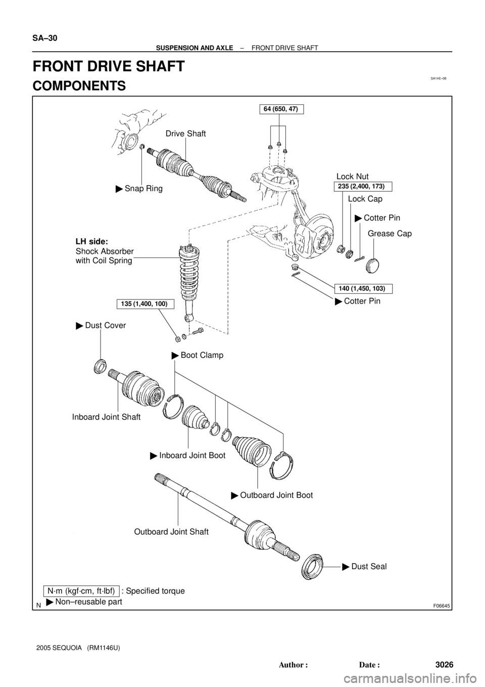
SA14E±08
F06645
� Snap Ring
Drive Shaft
� Dust Cover
Inboard Joint Shaft
� Inboard Joint Boot
� Outboard Joint Boot
� Boot Clamp
� Dust Seal Outboard Joint Shaft
� Cotter Pin� Cotter Pin
Grease Cap Lock Cap Lock Nut
235 (2,400, 173)
140 (1,450, 103)
� Non±reusable part
N´m (kgf´cm, ft´lbf) : Specified torqueShock Absorber
with Coil Spring
135 (1,400, 100)
LH side:
64 (650, 47)
SA±30
± SUSPENSION AND AXLEFRONT DRIVE SHAFT
3026 Author�: Date�:
2005 SEQUOIA (RM1146U)
FRONT DRIVE SHAFT
COMPONENTS