Page 3035 of 4323
SA24L±03
F06624
R12863
SST
R13233
± SUSPENSION AND AXLEFRONT DRIVE SHAFT
SA±31
3027 Author�: Date�:
2005 SEQUOIA (RM1146U)
REMOVAL
1. REMOVE FRONT WHEEL
2. REMOVE ENGINE UNDER COVER
3. DRAIN DIFFERENTIAL OIL
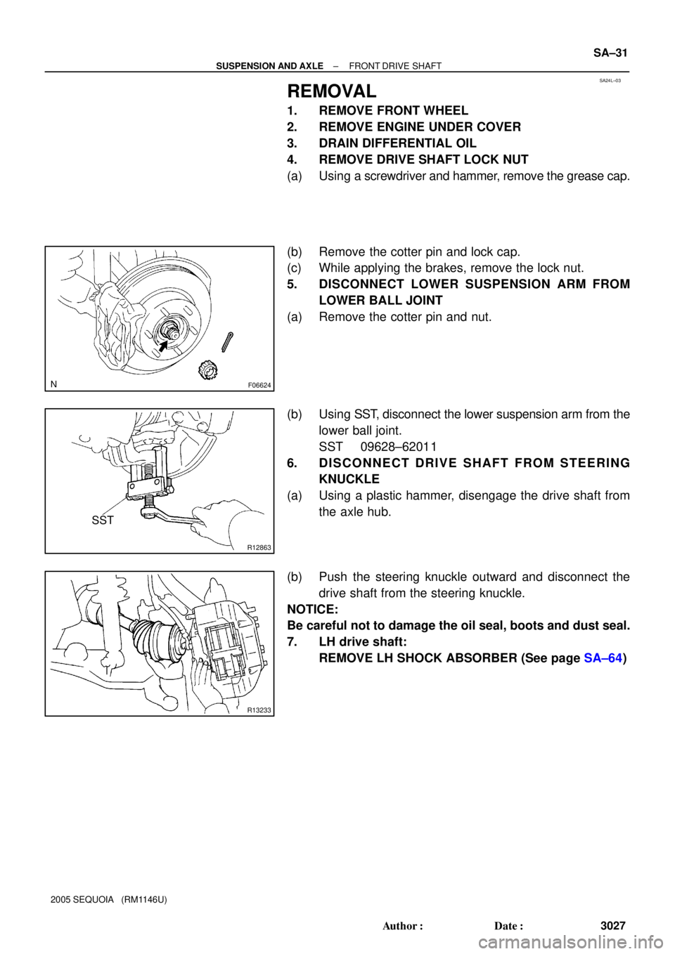
4. REMOVE DRIVE SHAFT LOCK NUT
(a) Using a screwdriver and hammer, remove the grease cap.
(b) Remove the cotter pin and lock cap.
(c) While applying the brakes, remove the lock nut.
5. DISCONNECT LOWER SUSPENSION ARM FROM
LOWER BALL JOINT
(a) Remove the cotter pin and nut.
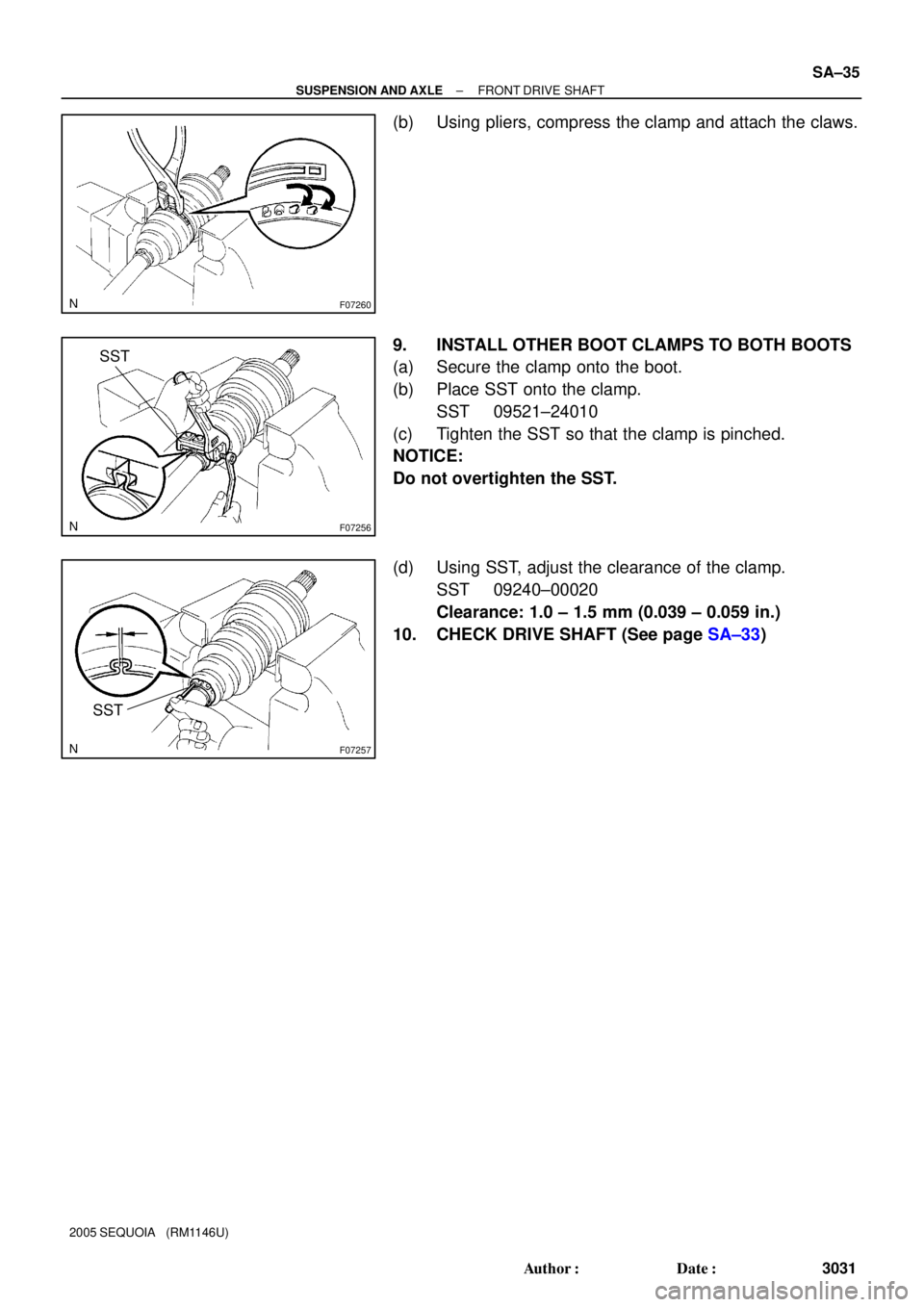
(b) Using SST, disconnect the lower suspension arm from the
lower ball joint.
SST 09628±62011
6. DISCONNECT DRIVE SHAFT FROM STEERING
KNUCKLE
(a) Using a plastic hammer, disengage the drive shaft from
the axle hub.
(b) Push the steering knuckle outward and disconnect the
drive shaft from the steering knuckle.
NOTICE:
Be careful not to damage the oil seal, boots and dust seal.
7. LH drive shaft:
REMOVE LH SHOCK ABSORBER (See page SA±64)
Page 3037 of 4323

DISASSEMBLY
1. CHECK DRIVE SHAFT
(a) Check")
SA24M±03
F06646
F07259
W03190
Matchmarks
F06647
SST
F06648
SST
± SUSPENSION AND AXLEFRONT DRIVE SHAFT
SA±33
3029 Author�: Date�:
2005 SEQUOIA (RM1146U)
DISASSEMBLY
1. CHECK DRIVE SHAFT
(a) Check to see that there is no remarkable play in the out-
board joint.
(b) Check to see that the inboard joint slides smoothly in the
thrust direction.
(c) Check to see that there is no remarkable play in the radial
direction of the inboard joint.
(d) Check the boots for damage.
2. REMOVE INBOARD AND OUTBOARD JOINT BOOT
CLAMPS
(a) Using pliers, pinch the claws to compress the large in-
board joint boot clamp and remove it.
(b) Using a side cutter, cut the small inboard joint boot clamp
and remove it.
(c) Using a side cutter, cut the 2 outboard joint boot clamps
and remove them.
3. REMOVE INBOARD JOINT SHAFT FROM OUTBOARD
JOINT SHAFT
(a) Place matchmarks on the inboard and outboard joint
shafts.
NOTICE:
Do not punch the marks.
(b) Using a snap ring expander, pull out the outboard joint
shaft while expanding the snap ring.
4. REMOVE INBOARD AND OUTBOARD JOINT BOOTS
5. REMOVE DUST SEAL
Using SST and a press, remove the dust seal.
SST 09950±00020
6. REMOVE DUST COVER
Using SST and a press, remove the dust cover.
SST 09950±00020
Page 3038 of 4323

REASSEMB")
SA14H±06
F06649
W03195
Inboard Joint Boot Outboard Joint Boot
Vinyl Tape
W03218
Matchmarks
F06650
SA±34
± SUSPENSION AND AXLEFRONT DRIVE SHAFT
3030 Author�: Date�:
2005 SEQUOIA (RM1146U)
REASSEMBLY
1. INSTALL DUST COVER
Using a screwdriver and hammer, install a new dust cover.
2. INSTALL DUST SEAL
Using a screwdriver and hammer, install a new dust seal.
3. TEMPORARILY INSTALL OUTBOARD AND INBOARD
JOINT BOOTS AND NEW BOOT CLAMPS
HINT:
�Before installing the boots, wrap the spline of the out-
board joint shaft with vinyl tape to prevent the boots from
bearing damaged.
�Before installing the boots, place 3 new clamps to the
small boot ends and large boot end (outboard joint side).
4. INSTALL INBOARD JOINT SHAFT TO OUTBOARD
JOINT SHAFT
Align the matchmarks placed before disassembly, and using a
snap ring expander, put in the inboard joint shaft while expand-
ing the snap ring.
5. INSTALL BOOT TO OUTBOARD JOINT
Before assembling the boot, pack the outboard joint and boot
with grease in the boot kit.
Grease capacity (Color = Black):
205 ± 225 g (7.23 ± 7.94 oz.)
6. INSTALL BOOT TO INBOARD JOINT SHAFT
(a) Pack the inboard joint and boot with grease in the boot kit.
Grease capacity (Color = Black):
190 ± 210 g (6.70 ± 7.41 oz.)
(b) Temporarily install the boot to the inboard joint shaft.
7. CHECK DRIVE SHAFT LENGTH
(a) Make sure that the 2 boots are on the shaft groove.
(b) Make sure that the 2 boots are not stretched or contracted
when the drive shaft is at standard length.
Drive shaft standard length:
523.5 ± 2.0 mm (20.610 ± 0.079 in.)
8. INSTALL LARGE INBOARD JOINT BOOT CLAMP TO
INBOARD JOINT SHAFT BOOT
(a) Place the large inboard joint boot clamp.
Page 3039 of 4323
F07260
F07256
SST
F07257
SST
± SUSPENSION AND AXLEFRONT DRIVE SHAFT
SA±35
3031 Author�: Date�:
2005 SEQUOIA (RM1146U)
(b) Using pliers, compress the clamp and attach the claws.
9. INSTALL OTHER BOOT CLAMPS TO BOTH BOOTS
(a) Secure the clamp onto the boot.
(b) Place SST onto the clamp.
SST 09521±24010
(c) Tighten the SST so that the clamp is pinched.
NOTICE:
Do not overtighten the SST.
(d) Using SST, adjust the clearance of the clamp.
SST 09240±00020
Clearance: 1.0 ± 1.5 mm (0.039 ± 0.059 in.)
10. CHECK DRIVE SHAFT (See page SA±33)
Page 3040 of 4323

INSTALLATION
1. INSTALL DRIVE SHAFT TO DIFFERENTIAL
(a) Install a new snap ring to the inboard jo")
SA14I±10
SA±36
± SUSPENSION AND AXLEFRONT DRIVE SHAFT
3032 Author�: Date�:
2005 SEQUOIA (RM1146U)
INSTALLATION
1. INSTALL DRIVE SHAFT TO DIFFERENTIAL
(a) Install a new snap ring to the inboard joint shaft.
(b) Apply gear oil to the inboard joint shaft and differential case sliding surface.
(c) Set the snap ring with opening side facing downward.
(d) Using a brass bar and hammer, install the drive shaft.
NOTICE:
Be careful not to damage the dust cover and oil seal.
HINT:
Whether the inboard joint shaft is in contact with the pinion shaft or not can be known from the sound or feel-
ing when driving.
(e) Check that there is 2 ± 3 mm (0.08 ± 0.12 in.) of play in the axial direction.
(f) Check that the drive shaft cannot be removed by hand.
2. LH drive shaft:
INSTALL LH SHOCK ABSORBER (See page SA±70)
3. CONNECT DRIVE SHAFT TO STEERING KNUCKLE
NOTICE:
Be careful not to damage the oil seal, boots and dust seal.
4. CONNECT LOWER SUSPENSION ARM TO LOWER BALL JOINT
(a) Connect the lower suspension arm to the lower ball joint.
(b) Install the nut and a new cotter pin.
If the holes for the cotter pin are not aligned, tighten the nut further up to 60°.
HINT:
Face the hole for the cotter pin forward.
Torque: 140 N´m (1,450 kgf´cm, 103 ft´lbf)
5. INSTALL DRIVE SHAFT LOCK NUT
(a) While applying brakes, install the nut.
Torque: 235 N´m (2,400 kgf´cm, 173 ft´lbf)
(b) Install the lock cap and a new cotter pin.
If the holes for the cotter pin are not aligned, tighten the nut further up to 60°.
6. FILL DIFFERENTIAL WITH HYPOID GEAR OIL (See page SA±38)
7. INSTALL ENGINE UNDER COVER
8. INSTALL FRONT WHEEL
Torque: 110 N´m (1,150 kgf´cm, 83 ft´lbf)
Page 3085 of 4323
SA23Z±04
F07279
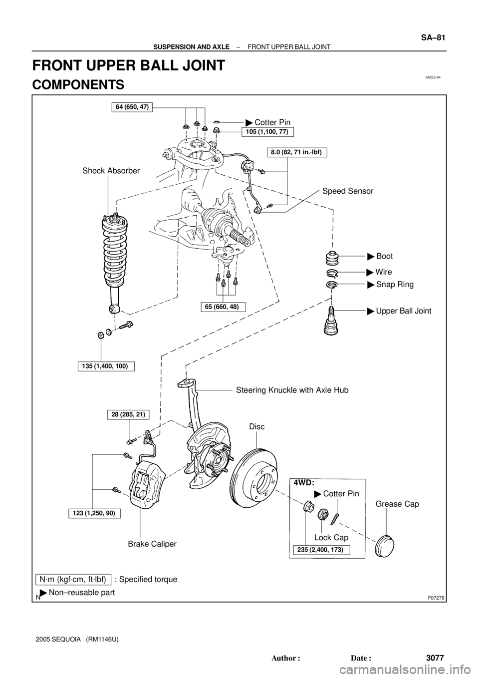
N´m (kgf´cm, ft´lbf) : Specified torque
� Non±reusable part� Boot
� Wire
� Snap Ring
� Upper Ball Joint
64 (650, 47)
Brake Caliper� Cotter Pin
105 (1,100, 77)
Shock Absorber
123 (1,250, 90)
28 (285, 21)
Steering Knuckle with Axle Hub
Disc
4WD:
� Cotter Pin
235 (2,400, 173)
Lock Cap
Grease Cap
8.0 (82, 71 in.´lbf)
Speed Sensor
135 (1,400, 100)
65 (660, 48)
± SUSPENSION AND AXLEFRONT UPPER BALL JOINT
SA±81
3077 Author�: Date�:
2005 SEQUOIA (RM1146U)
FRONT UPPER BALL JOINT
COMPONENTS
Page 3086 of 4323
SA240±03
R12864
SST
Deep Socket
Wrench SA±82
± SUSPENSION AND AXLEFRONT UPPER BALL JOINT
3078 Author�: Date�:
2005 SEQUOIA (RM1146U)
REMOVAL
1. REMOVE STEERING KNUCKLE WITH AXLE HUB
(See page SA±22)
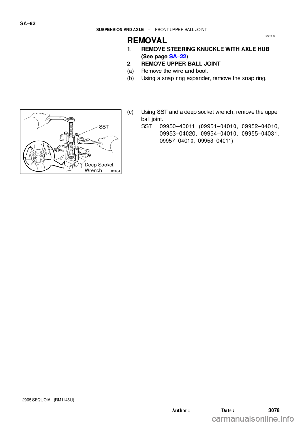
2. REMOVE UPPER BALL JOINT
(a) Remove the wire and boot.
(b) Using a snap ring expander, remove the snap ring.
(c) Using SST and a deep socket wrench, remove the upper
ball joint.
SST 09950±40011 (09951±04010, 09952±04010,
09953±04020, 09954±04010, 09955±04031,
09957±04010, 09958±04011)
Page 3087 of 4323
SA241±03
R12776
± SUSPENSION AND AXLEFRONT UPPER BALL JOINT
SA±83
3079 Author�: Date�:
2005 SEQUOIA (RM1146U)
INSPECTION
1. INSPECT UPPER BALL JOINT BOOT FOR DAMAGE
2. INSPECT UPPER BALL JOINT FOR ROTATION
CONDITION
(a) As shown in the illustration, flip the ball joint stud back and
forth 5 times before installing the nut.
(b) Using a torque wrench, turn the nut continuously 1 turn
per 2 ± 4 seconds and take the torque reading on the 5th
turn.
Turning torque:
0.7 ± 4.4 N´m (7 ± 45 kgf´cm, 6 ± 39 in.´lbf)