Page 424 of 4323
B17411E8
IGT8
IGT2IGT4
IGT5 IGT6IGT3
IGT7IGT1E1(+)(±) (+) (+)
(+)
(+)
(+)
(+)
(+)
E6
DI±230
± DIAGNOSTICSENGINE
424 Author�: Date�:
2005 SEQUOIA (RM1146U)
5 Check voltage between terminals IGT1 ± IGT8 and E1 of ECM connector.
PREPARATION:
Turn the ignition switch to ON.
CHECK:
Measure the voltage between terminals the E8 and E6 ECM
connectors when the engine is cranked.
OK:
Standard:
Tester ConnectionSpecified Condition
IGT1 (E8±8) ± E1 (E6±1)More than 0.1 V or less than 4.5 V
IGT2 (E8±15) ± E1 (E6±1)More than 0.1 V or less than 4.5 V
IGT3 (E8±11) ± E1 (E6±1)More than 0.1 V or less than 4.5 V
IGT4 (E8±10) ± E1 (E6±1)More than 0.1 V or less than 4.5 V
IGT5 (E8±13) ± E1 (E6±1)More than 0.1 V or less than 4.5 V
IGT6 (E8±12) ± E1 (E6±1)More than 0.1 V or less than 4.5 V
IGT7 (E8±14) ± E1 (E6±1)More than 0.1 V or less than 4.5 V
IGT8 (E8±9) ± E1 (E6±1)More than 0.1 V or less than 4.5 V
NG Replace ECM (See page SF±80).
OK
Page 425 of 4323
B17411E8
IGT8
IGT2IGT4
IGT5 IGT6IGT3
IGT7IGT1E1(+)(±) (+) (+)
(+)
(+)
(+)
(+)
(+)
E6
± DIAGNOSTICSENGINE
DI±231
425 Author�: Date�:
2005 SEQUOIA (RM1146U)
6 Disconnect ignition coil with igniter connector, and check voltage between ter-
minals IGT1 ± IGT8 and E1 of ECM connector.
PREPARATION:
(a) Disconnect the I1, I2, I3, I4, I5, I6, I7 or I8 ignition coil with
igniter connector.
(b) Turn the ignition switch to ON.
CHECK:
Measure the voltage between terminals the E6 and E8 ECM
connectors when the engine is cranked.
OK:
Standard:
Tester ConnectionSpecified Condition
IGT1 (E8±8) ± E1 (E6±1)4.5 V or more
IGT2 (E8±15) ± E1 (E6±1)4.5 V or more
IGT3 (E8±11) ± E1 (E6±1)4.5 V or more
IGT4 (E8±10) ± E1 (E6±1)4.5 V or more
IGT5 (E8±13) ± E1 (E6±1)4.5 V or more
IGT6 (E8±12) ± E1 (E6±1)4.5 V or more
IGT7 (E8±14) ± E1 (E6±1)4.5 V or more
IGT8 (E8±9) ± E1 (E6±1)4.5 V or more
NG Replace ECM (See page SF±80).
OK
Page 426 of 4323
A21025
Wire Harness Side:
I1
I2
I3I4
I5I6
I7I8Ignition Coil with
Igniter Connector
DI±232
± DIAGNOSTICSENGINE
426 Author�: Date�:
2005 SEQUOIA (RM1146U)
7 Check ignition coil with igniter power source circuit.
PREPARATION:
(a) Disconnect the I1, I2, I3, I4, I5, I6, I7 or I8 ignition coil with
igniter connector.
(b) Turn the ignition switch to ON.
CHECK:
Measure the voltage between the terminal of the wire harness
side connector and body ground.
OK:
Standard:
Tester ConnectionSpecified Condition
I1±1 ± Body ground
I2±1 ± Body ground
I3±1 ± Body ground
I4±1 ± Body ground9t 14VI5±1 ± Body ground9 to 14 V
I6±1 ± Body ground
I7±1 ± Body ground
I8±1 ± Body ground
OK Repair ignition coil with igniter.
NG
Page 427 of 4323

8 Ch")
A21025
Wire Harness Side:
I1
I2
I3I4
I5I6
I7I8Ignition Coil with Igniter
A21378
Wire Harness Side:
I18
Ignition SwitchIG2
± DIAGNOSTICSENGINE
DI±233
427 Author�: Date�:
2005 SEQUOIA (RM1146U)
8 Check for open and short in harness and connector between ignition switch and
ignition coil with igniter.
PREPARATION:
(a) Disconnect the I1, 2, I3, I4, I5, I6, I7 or I8 ignition coil with
igniter connector.
(b) Disconnect the I18 ignition switch connector.
CHECK:
Measure the resistance between the wire harness side connec-
tors.
OK:
Standard:
Tester ConnectionSpecified Condition
Ignition coil (I1±1) ± IG2 (I18±6)Below 1 W
Ignition coil (I2±1) ± IG2 (I18±6)Below 1 W
Ignition coil (I3±1) ± IG2 (I18±6)Below 1 W
Ignition coil (I4±1) ± IG2 (I18±6)Below 1 W
Ignition coil (I5±1) ± IG2 (I18±6)Below 1 W
Ignition coil (I6±1) ± IG2 (I18±6)Below 1 W
Ignition coil (I7±1) ± IG2 (I18±6)Below 1 W
Ignition coil (I8±1) ± IG2 (I18±6)Below 1 W
Ignition coil (I1±1) or IG2 (I18±6) ±
Body ground10 kW or higher
Ignition coil (I2±1) or IG2 (I18±6) ±
Body ground10 kW or higher
Ignition coil (I3±1) or IG2 (I18±6) ±
Body ground10 kW or higher
Ignition coil (I4±1) or IG2 (I18±6) ±
Body ground10 kW or higher
Ignition coil (I5±1) or IG2 (I18±6) ±
Body ground10 kW or higher
Ignition coil (I6±1) or IG2 (I18±6) ±
Body ground10 kW or higher
Ignition coil (I7±1) or IG2 (I18±6) ±
Body ground10 kW or higher
Ignition coil (I8±1) or IG2 (I18±6) ±
Body ground10 kW or higher
NG Repair or replace harness or connector.
OK
Replace ignition coil with igniter.
Page 431 of 4323

B17411
ECM Connector
E1AIDI
A16555
AIR INJ CHECK
AIR PUMP............................ON
EASV ............................OPEN
ASV1. .............................OPEN
ASV2...............................OPEN
A/F BANK1.......................19.05
A/F BANK2.......................19.05
PRESSURE....................17 kPa
PULSATION..............25.39 kPa
AI STATUS...........................OK
Remaining Time 05 sec.
Press [EXIT] to quit
Example: 80% Duty Signal5 V/DIV.
GND
20 ms/DIV.
± DIAGNOSTICSENGINE
DI±237
431 Author�: Date�:
2005 SEQUOIA (RM1146U)
INSPECTION PROCEDURE
HINT:
The diagnostic information output from the AID can be confirmed by connecting an oscilloscope to the diag-
nostic information terminal of the AID. It narrows the trouble area to read the waveform on the oscilloscope
when performing the AI system intrusive operation function provided in the SYSTEM CHECK.
(1) Start the engine and warm it up.
(2) Turn the ignition switch to OFF.
(3) Connect a hand±held tester to the DLC3.
(4) Connect an oscilloscope probe to the AIDI terminal
of the ECM.
(5) Start the engine and turn the tester ON.
(6) On the tester, select the following menu items:
DIAGNOSIS / ENHANCED OBD II / SYSTEM
CHECK / AIR INJ CHECK / MANUAL OPERATION
/ OPERATION 1 and 2.
HINT:
OPERATION 1: AP: OFF, EASV:CLOSE, ASV1:CLOSE,
ASV2:CLOSE
OPERATION 2: AP: ON, EASV:OPEN, ASV1:OPEN,
ASV2:OPEN
(7) Monitor the voltage output of the AID (duty ratio sig-
nal).
Oscilloscope range:
ItemsContents
TerminalsCH1: AIDI ± E1
Equipment Settings5 V/Division, 20 to 40 ms/Division
ConditionsIdling
NOTICE:
�This AIR INJECTION CHECK only allows technicians to operate the AI system for 5 seconds.
Furthermore, the check can be performed 4 times a trip. If the test is repeated, intervals of at
least 30 seconds are required between checks.
While the AI system operation using the hand±held tester is prohibited, the tester displays the
prohibition (WAIT or ERROR). If the ERROR (AI STATUS NG) is displayed on the tester, stop the
engine for 10 minutes and then try again.
�Performing the AIR INJ CHECK over and over again may cause the damage in the secondary
air injection system. If necessary, put an interval of several minutes between tests to prevent
overheating the system.
Page 433 of 4323

HINT:
�Using the AIR INJ CHECK operation of the SYSTEM CHECK provi")
B17440
A46
Air Switching Valve Connector Wire Harness Side:
± DIAGNOSTICSENGINE
DI±239
433 Author�: Date�:
2005 SEQUOIA (RM1146U)
HINT:
�Using the AIR INJ CHECK operation of the SYSTEM CHECK provided in the hand±held tester func-
tion, conditions for air±fuel ratio and pressure in the secondary air injection system passage can be
checked while the secondary air injection system operating. It helps technicians to troubleshoot the
system when it malfunctioning.
�Read freeze frame data using a hand±held tester. Freeze frame data record the engine condition when
malfunctions are detected. When troubleshooting, freeze frame data can help determine if the vehicle
was moving or stationary, if the engine was warmed up or not, if the air±fuel ratio was lean or rich, and
other data, from the time the malfunction occurred.
1 Check voltage between terminal 1 of air switching valve connector and body
ground.
PREPARATION:
(a) Remove the intake manifold (see page EM±36).
(b) Disconnect the A46 air switching valve connector.
(c) Connect the hand±held tester to the DLC3.
(d) Turn the ignition switch ON and turn the tester ON.
CHECK:
(a) When the air switching valve is operated using the hand±
held tester, measure voltage between terminal A46±1 of
the air switching valve connector and body ground.
(b) Select the following menu items: DIAGNOSIS/EN-
HANCED OBD II/SYSTEM CHECK/ AIR INJ CHECK/
MANUAL OPERATION/OPERATION 1 and 4
HINT:
OPERATION 1: AP:OFF, EASV:CLOSE, ASV1:CLOSE,
ASV2:CLOSE
OPERATION 4: AP:OFF, EASV:OPEN, ASV1:CLOSE,
ASV2:CLOSE
NOTICE:
This test only allows technicians to operate the AI system
for 5 seconds. Furthermore, the test can be performed 4
times a trip. If the test is repeated, intervals of at least 30
seconds are required between tests.
While the AI system operation using the hand±held tester
is prohibited, the tester displays the prohibition (WAIT or
ERROR). If the ERROR (AI STATUS NG) is displayed on the
tester, stop the engine for 10 minutes and then try again..
OK:
Standard:
Tester operationTester ConnectionSpecified Condition
Operation 4A46±1 ± Body ground10 V or more
Operation 1A46±1 ± Body groundBelow 1.0 V
NG Go to step 4.
OK
Page 434 of 4323
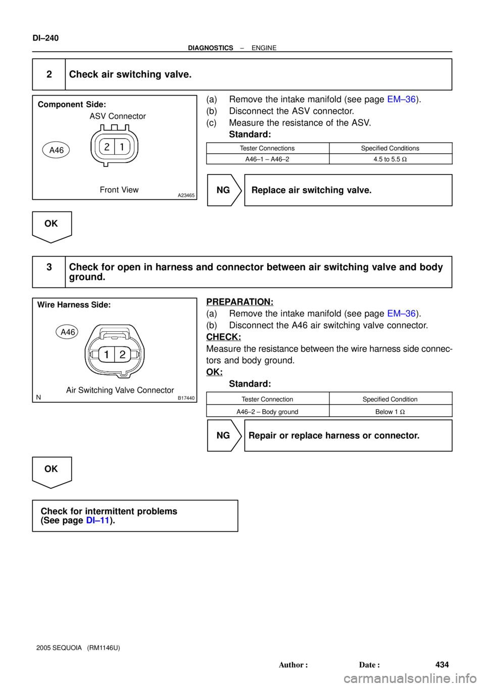
A23465
Component Side:
ASV Connector
Front View
A46
B17440
A46
Air Switching Valve Connector Wire Harness Side:
DI±240
± DIAGNOSTICSENGINE
434 Author�: Date�:
2005 SEQUOIA (RM1146U)
2 Check air switching valve.
(a) Remove the intake manifold (see page EM±36).
(b) Disconnect the ASV connector.
(c) Measure the resistance of the ASV.
Standard:
Tester ConnectionsSpecified Conditions
A46±1 ± A46±24.5 to 5.5 W
NG Replace air switching valve.
OK
3 Check for open in harness and connector between air switching valve and body
ground.
PREPARATION:
(a) Remove the intake manifold (see page EM±36).
(b) Disconnect the A46 air switching valve connector.
CHECK:
Measure the resistance between the wire harness side connec-
tors and body ground.
OK:
Standard:
Tester ConnectionSpecified Condition
A46±2 ± Body groundBelow 1 W
NG Repair or replace harness or connector.
OK
Check for intermittent problems
(See page DI±11).
Page 435 of 4323
B17444
Wire Harness Side:
Air Injection Driver Connector
A41
VV
B17440
A46
Air Switching Valve Connector Wire Harness Side:
± DIAGNOSTICSENGINE
DI±241
435 Author�: Date�:
2005 SEQUOIA (RM1146U)
4 Check for open and short in harness and connector between air injection driver
and air switching valve.
PREPARATION:
(a) Remove the intake manifold (see page EM±36).
(b) Disconnect the A41 air injection driver connector.
(c) Disconnect the A46 air switching valve connector.
CHECK:
Measure the resistance between the wire harness side connec-
tors.
OK:
Standard:
Tester ConnectionSpecified Condition
VV (A41±6) ± A46±1Below 1 W
VV (A41±6) or A46±1 ±
Body ground10 kW or higher
NG Repair or replace harness or connector.
OK
Replace air injection driver.