Page 2075 of 4323

± DIAGNOSTICSBACK DOOR CONTROL SYSTEM
DI±1873
2067 Author�: Date�:
2005 SEQUOIA (RM1146U)
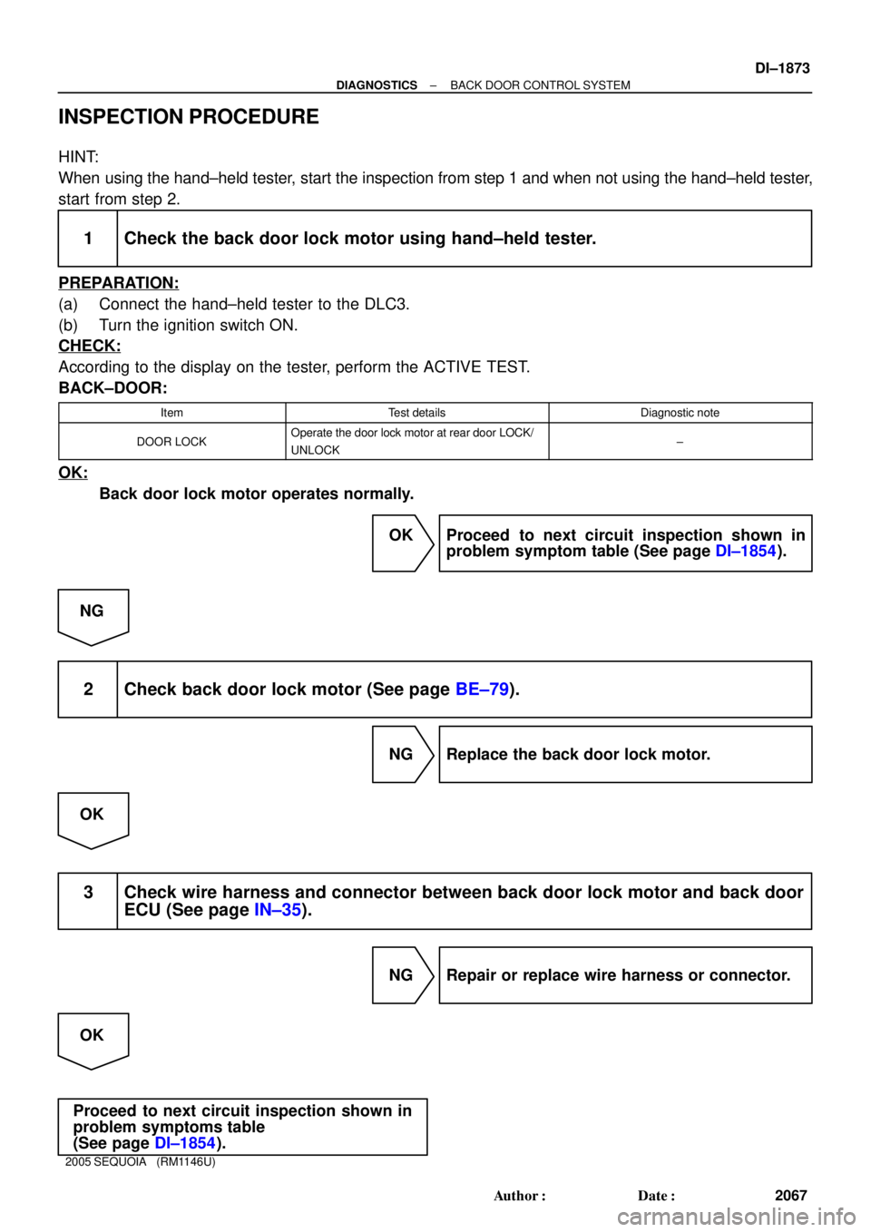
INSPECTION PROCEDURE
HINT:
When using the hand±held tester, start the inspection from step 1 and when not using the hand±held tester,
start from step 2.
1 Check the back door lock motor using hand±held tester.
PREPARATION:
(a) Connect the hand±held tester to the DLC3.
(b) Turn the ignition switch ON.
CHECK:
According to the display on the tester, perform the ACTIVE TEST.
BACK±DOOR:
ItemTest detailsDiagnostic note
DOOR LOCKOperate the door lock motor at rear door LOCK/
UNLOCK±
OK:
Back door lock motor operates normally.
OK Proceed to next circuit inspection shown in
problem symptom table (See page DI±1854).
NG
2 Check back door lock motor (See page BE±79).
NG Replace the back door lock motor.
OK
3 Check wire harness and connector between back door lock motor and back door
ECU (See page IN±35).
NG Repair or replace wire harness or connector.
OK
Proceed to next circuit inspection shown in
problem symptoms table
(See page DI±1854).
Page 2084 of 4323
I18725
Back Door ECU
BKUL
12G B12
Back Door Key Lock and Unlock SW
3R±W
LKEYE
BKL 5 4 B1019
B10
B10 DI±1882
± DIAGNOSTICSBACK DOOR CONTROL SYSTEM
2076 Author�: Date�:
2005 SEQUOIA (RM1146U)
Back door key lock and unlock switch circuit
CIRCUIT DESCRIPTION
The back door ECU operates the back door lock motor based on information from the back door key lock
and unlock switch.
The back door power window goes up when the key is inserted into the cylinder and turned to the LOCK
position. The window goes down when the key is turned to the UNLOCK position.
WIRING DIAGRAM
DI94L±05
Page 2085 of 4323

± DIAGNOSTICSBACK DOOR CONTROL SYSTEM
DI±1883
2077 Author�: Date�:
2005 SEQUOIA (RM1146U)
INSPECTION PROCEDURE
HINT:
When using the hand±held tester, start the inspection from step 1 and when not using the hand±held tester,
start from step 2.
1 Check the back door key lock and unlock switch using hand±held tester.
PREPARATION:
(a) Connect the hand±held tester to the DLC3.
(b) Turn the ignition switch ON.
CHECK:
According to the display on the tester, read the DATA LIST.
BACK±DOOR:
ItemMeasurement Item/
Display (Range)Normal ConditionDiagnostic Note
KEY SW (UNLOCK)Unlock SW linked with
the key/ON or OFFON: Back door lock is in unlock position
OFF: Back door lock is in lock position±
KEY SW (LOCK)Unlock SW linked with
the key/ON or OFFON: Back door lock is in lock position
OFF: Back door lock is in unlock position±
UP/DOOR KEY
Back door key lock
and unlock switch
linked window open
and close/AVAIL or
NOT AVL
AVAIL: Key±linked open and close SET
NOT AVL: Key±linked open and close UNSET*1
DOWN/DOOR KEY
Back door key lock
and unlock switch
linked window open
and close/AVAIL or
NOT AVL
AVAIL: Key±linked open and close SET
NOT AVL: Key±linked open and close UNSET*1
*1: When the ignition key is not in the key cylinder and the back door is locked, turning and holding the back
door key in the lock position for 1.5 seconds or more activates the back door ECU to operate the power win-
dow motor and close the power window.
Similarly, turning and holding the back door key in the unlock position for 1.5 seconds or more when the back
door is unlocked will open the power window.
OK:
Indication on the tester switches between ON and OFF in accordance with the back door key
lock and unlock switch status.
OK Proceed to next circuit inspection shown in
problem symptoms table (See page DI±1854).
NG
Page 2086 of 4323
DI±1884
± DIAGNOSTICSBACK DOOR CONTROL SYSTEM
2078 Author�: Date�:
2005 SEQUOIA (RM1146U)
2 Check the back door key lock and unlock switch (See page BE±79).
NG Replace the back door key lock and unlock
switch.
OK
3 Check wire harness and connector between back door key lock and unlock
switch and back door ECU (See page IN±35).
NG Repair or replace wire harness or connector.
OK
Proceed to next circuit inspection shown in
problem symptoms table
(See page DI±1854).
Page 2096 of 4323

DIDFA±01
I27698
B5
B6B7
DI±1894
± DIAGNOSTICSMULTIPLEX COMMUNICATION SYSTEM
2088 Author�: Date�:
2005 SEQUOIA (RM1146U)
TERMINALS OF ECU
1. CHECK BODY ECU
(a) Disconnect the B5, B6 and B7 ECU connectors.
(b) Measure the resistance or voltage of each terminal of the wire harness side connector.
Standard:
Symbols (Terminal No.)Wiring ColorTerminal DescriptionConditionSpecified Condition
BDR (B6±2) ±
Body groundL±W ± Body ground+B (BATT) power supplyAlways10 to 14 V
IG (B7±6) ± Body groundB±R ± Body groundIgnition power supplyIgnition switch ON10 to 14 V
ACC (B7±10) ±
Body groundGR ± Body groundACC power supplyIgnition switch ACC10 to 14 V
OBD2 (B5±2) ±
Body groundG±R ± Body groundBus º+º lineDuring transmissionPulse generation
S+B (B6±1) ± Body groundW±L ± Body ground+B (BATT) power supplyAlways10 to 14 V
BECU (B6±5) ±
Body groundW±R ± Body ground+B (BATT) power supplyAlways10 to 14 V
WIG (B7±5) ± Body groundL±Y ± Body groundIgnition power supplyIgnition switch ON10 to 14 V
MPX3 (B7±20) ±
Body groundG±O ± Body groundMPX lineAlways10 kW or higher
MPX2 (B5±24) ±
Body groundL±Y ± Body groundMPX lineAlways10 kW or higher
MPX1 (B7±22) ±
Body groundW±L ± Body groundMPX lineAlways10 kW or higher
GND1 (B6±6) ±
Body groundW±B ± Body groundGroundAlwaysBelow 1 W
PRG ± GND1
(B5±5 ± B6±6)V ± W±BWireless transmitter signal
groundWireless door look receiver
communication circuit±
RDA ± GND1
(B5±4 ± B6±6)R±G ± W±BWireless transmitter signal
inputWireless door lock control
system is operatedBelow 1 V
RDA ± GND1
(B5±4 ± B6±6)R±G ± W±BWireless transmitter signal
inputWireless door lock control
system is not operated10 to 14 V
GSW
(B6±16)GR±RAir bag sensor commu-
nication signalAir bag sensor commu-
nication circuit±
CLTS (*1) ± GND1
(B6±12 ± B6±6)Y ± W±BAutomatic light control sen-
sor (Signal)Ignition switch OFFBelow 1 V
CLTS (*1) ± GND1
(B6±12 ± B6±6)Y ± W±BAutomatic light control sen-
sor (Signal)Ignition switch ONSignal waveform
CLTE (*1) ± GND1
(B6±3 ± B6±6)BR ± W±BAutomatic light control sen-
sor (Ground)AlwaysBelow 1 V
Page 2107 of 4323

DI3IR±10
± DIAGNOSTICSMULTIPLEX COMMUNICATION SYSTEM
DI±1905
2099 Author�: Date�:
2005 SEQUOIA (RM1146U)
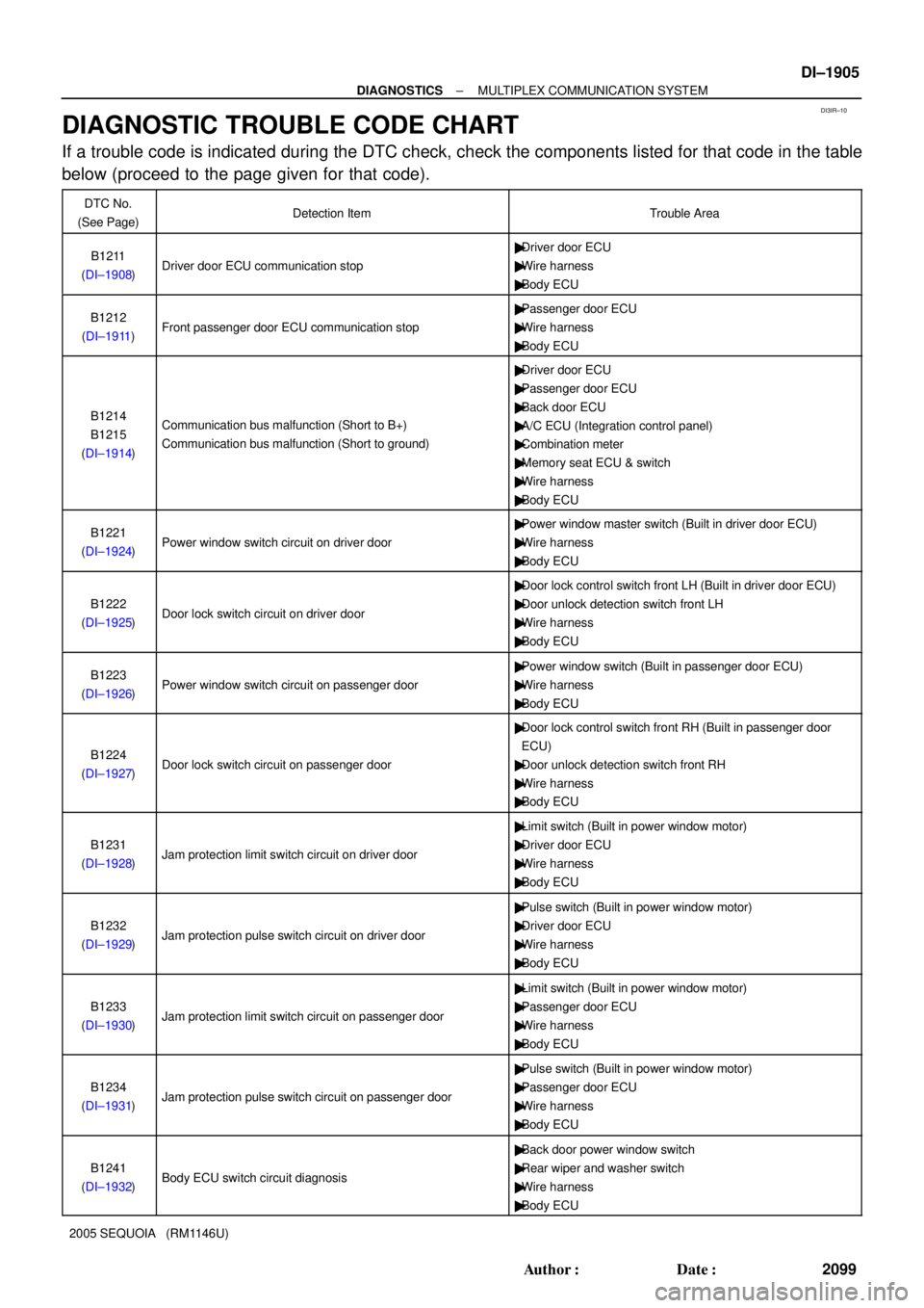
DIAGNOSTIC TROUBLE CODE CHART
If a trouble code is indicated during the DTC check, check the components listed for that code in the table
below (proceed to the page given for that code).
DTC No.
(See Page)Detection ItemTrouble Area
B1211
(DI±1908)Driver door ECU communication stop
�Driver door ECU
�Wire harness
�Body ECU
B1212
(DI±1911)Front passenger door ECU communication stop
�Passenger door ECU
�Wire harness
�Body ECU
B1214
B1215
(DI±1914)Communication bus malfunction (Short to B+)
Communication bus malfunction (Short to ground)
�Driver door ECU
�Passenger door ECU
�Back door ECU
�A/C ECU (Integration control panel)
�Combination meter
�Memory seat ECU & switch
�Wire harness
�Body ECU
B1221
(DI±1924)Power window switch circuit on driver door
�Power window master switch (Built in driver door ECU)
�Wire harness
�Body ECU
B1222
(DI±1925)Door lock switch circuit on driver door
�Door lock control switch front LH (Built in driver door ECU)
�Door unlock detection switch front LH
�Wire harness
�Body ECU
B1223
(DI±1926)Power window switch circuit on passenger door
�Power window switch (Built in passenger door ECU)
�Wire harness
�Body ECU
B1224
(DI±1927)Door lock switch circuit on passenger door
�Door lock control switch front RH (Built in passenger door
ECU)
�Door unlock detection switch front RH
�Wire harness
�Body ECU
B1231
(DI±1928)Jam protection limit switch circuit on driver door
�Limit switch (Built in power window motor)
�Driver door ECU
�Wire harness
�Body ECU
B1232
(DI±1929)Jam protection pulse switch circuit on driver door
�Pulse switch (Built in power window motor)
�Driver door ECU
�Wire harness
�Body ECU
B1233
(DI±1930)Jam protection limit switch circuit on passenger door
�Limit switch (Built in power window motor)
�Passenger door ECU
�Wire harness
�Body ECU
B1234
(DI±1931)Jam protection pulse switch circuit on passenger door
�Pulse switch (Built in power window motor)
�Passenger door ECU
�Wire harness
�Body ECU
B1241
(DI±1932)Body ECU switch circuit diagnosis
�Back door power window switch
�Rear wiper and washer switch
�Wire harness
�Body ECU
Page 2108 of 4323

DI±1906
± DIAGNOSTICSMULTIPLEX COMMUNICATION SYSTEM
2100 Author�: Date�:
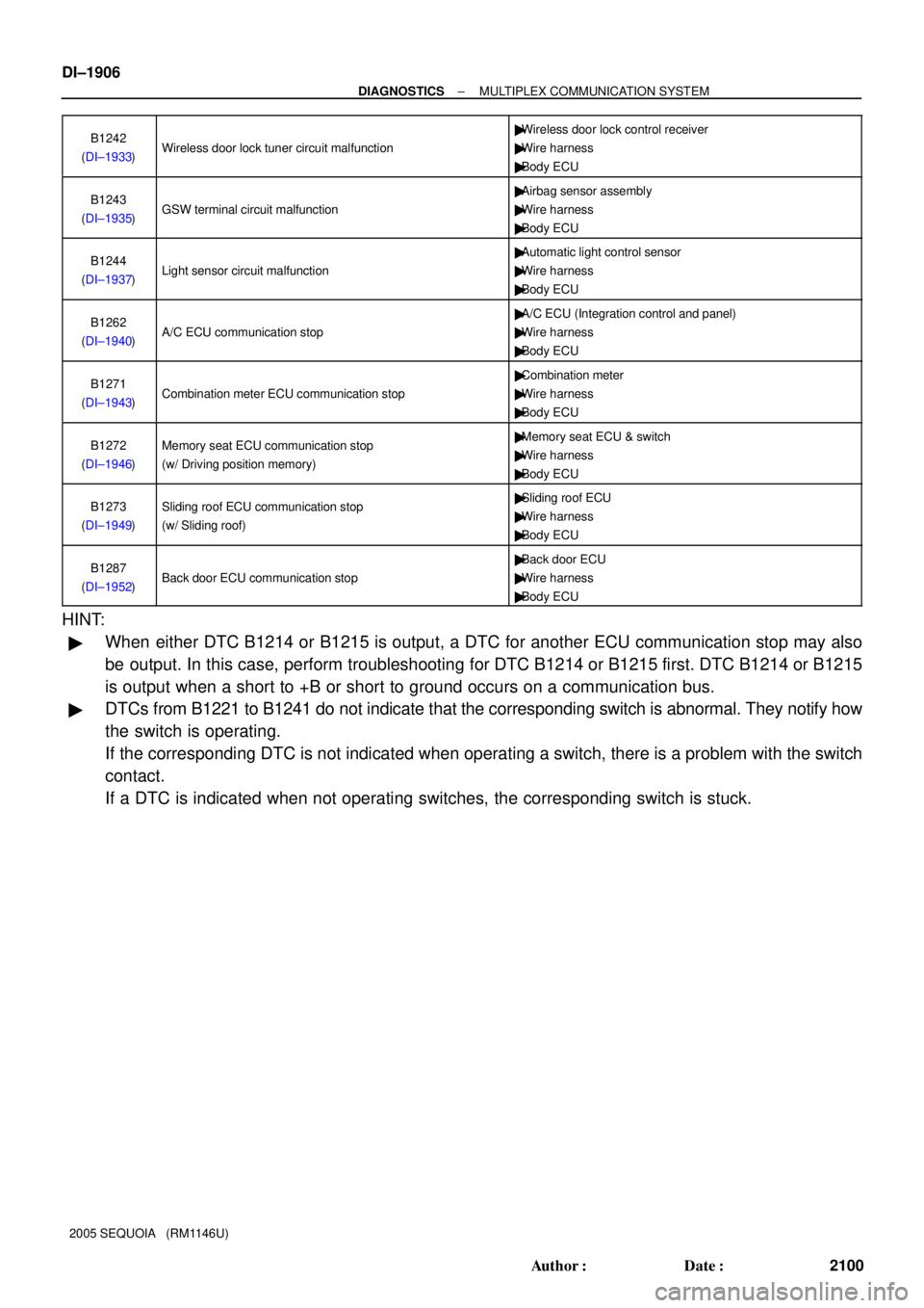
2005 SEQUOIA (RM1146U)B1242
(DI±1933)
Wireless door lock tuner circuit malfunction
�Wireless door lock control receiver
�Wire harness
�Body ECU
B1243
(DI±1935)GSW terminal circuit malfunction
�Airbag sensor assembly
�Wire harness
�Body ECU
B1244
(DI±1937)Light sensor circuit malfunction
�Automatic light control sensor
�Wire harness
�Body ECU
B1262
(DI±1940)A/C ECU communication stop
�A/C ECU (Integration control and panel)
�Wire harness
�Body ECU
B1271
(DI±1943)Combination meter ECU communication stop
�Combination meter
�Wire harness
�Body ECU
B1272
(DI±1946)Memory seat ECU communication stop
(w/ Driving position memory)�Memory seat ECU & switch
�Wire harness
�Body ECU
B1273
(DI±1949)Sliding roof ECU communication stop
(w/ Sliding roof)�Sliding roof ECU
�Wire harness
�Body ECU
B1287
(DI±1952)Back door ECU communication stop
�Back door ECU
�Wire harness
�Body ECU
HINT:
�When either DTC B1214 or B1215 is output, a DTC for another ECU communication stop may also
be output. In this case, perform troubleshooting for DTC B1214 or B1215 first. DTC B1214 or B1215
is output when a short to +B or short to ground occurs on a communication bus.
�DTCs from B1221 to B1241 do not indicate that the corresponding switch is abnormal. They notify how
the switch is operating.
If the corresponding DTC is not indicated when operating a switch, there is a problem with the switch
contact.
If a DTC is indicated when not operating switches, the corresponding switch is stuck.
Page 2111 of 4323
I28467
F18
Front Passenger Door ECUD22
Driver Door ECU
Body ECU
J/C
I18
Ignition Switch
Instrument Panel J/B
Sub J/B No. 3
F10
FL Block
Sub J/B No. 3Instrument Panel J/B
Engine Room R/B J8
J/C
Battery
IEECU±B
Short Pin
ECU±IG
AM1
PWR No. 1 J/CB7 IB1
II2
J6 J7
J37 J38IB1
IB1
IB1
3C 3A 1F 1C
1L
1E 1J
2D 2C1C
1F
3C 3A ALTIG1 AM1IB1MPX1
MPX2
GND
SIGCPUB
BDR MPX2
MPX1W±L
W±R
L±W G±B
W±B
B±RW±L
G±B
G±B
W±B
B±RW±R
W±L
B±Y
B±RB±R
W±L
L±W
W±RW
W±R
W±R BBD
AF
AA48
9 1122
23
251 3
13 20
13 8
21
88 4 4
1
1 6
12
48 5
11 23
1821
± DIAGNOSTICSMULTIPLEX COMMUNICATION SYSTEM
DI±1909
2103 Author�: Date�:
2005 SEQUOIA (RM1146U)
WIRING DIAGRAM