Page 3197 of 4323
BR10H±05
BR3753
BR±22
± BRAKEBRAKE BOOSTER ASSEMBLY
3189 Author�: Date�:
2005 SEQUOIA (RM1146U)
REMOVAL
1. REMOVE MASTER CYLINDER (See page BR±16)
2. DISCONNECT VACUUM HOSE FROM BRAKE
BOOSTER
3. DISCONNECT 2 VACUUM SWITCH CONNECTORS
FROM BRAKE BOOSTER
4. REMOVE FRONT DOOR SCUFF PLATE, COWL SIDE
TRIM BOARD, SIDE PANEL, LOWER FINISH PANEL
AND NO. 2 HEATER TO REGISTER DUCT (See page
BO±89)
5. REMOVE PEDAL RETURN SPRING
6. REMOVE CLIP AND CLEVIS PIN
7. REMOVE BRAKE BOOSTER
(a) Remove the 4 nuts, pull out the brake booster.
Torque: 13 N´m (130 kgf´cm, 9 ft´lbf)
(b) Remove the gasket from the brake booster bracket.
(c) Loosen the lock nut then remove the clevis.
Torque: 25 N´m (250 kgf´cm, 18 ft´lbf)
(d) Remove the check valve.
(e) Remove the 4 nuts, brake booster bracket and gasket
from the brake booster.
Torque: 25 N´m (250 kgf´cm, 18 ft´lbf)
Page 3247 of 4323
SR1F3±03
F17895
Steering Wheel Pad
Steering
Wheel
Column Lower
CoverCombination
SwitchSteering Column Assembly
Transmission Control
Cable Assembly
Lower LH Finish PanelColumn Hole
Cover No. 2
No. 2 Universal
Joint Assembly
No. 2 Heater to Register Dust Torx® Screw
35 (360, 26)
35 (360, 26)
8.0 (82, 71 in.´lbf)
26 (260, 19)
26 (260, 19)
8.8 (90, 78 in.´lbf)
50 (510, 37)
8.8 (90, 78 in.´lbf)
Front Door Scuff PlateCowl Side Trim
Hood Lock
Release Lever
8.0 (82, 71 in.´lbf)
Side Panel
No. 2 Intermediate
Shaft AssemblyBrake Pedal
Return Spring
Column Upper Cover
N´m (kgf´cm, ft´lbf): Specified torque
Steering Wheel Lower
No. 3 Cover
Steering Wheel Lower
No. 2 Cover
35 (360, 26)
Sliding Yoke
Torx® Screw SR±12
± STEERINGTILT STEERING COLUMN
3239 Author�: Date�:
2005 SEQUOIA (RM1146U)
TILT STEERING COLUMN
COMPONENTS
Page 3250 of 4323
F17896
A
BMatchmarks
F13260
F06703
± STEERINGTILT STEERING COLUMN
SR±15
3242 Author�: Date�:
2005 SEQUOIA (RM1146U)
5. REMOVE COMBINATION SWITCH WITH SPIRAL
CABLE
(a) Disconnect the 4 connectors.
(b) Disconnect the airbag connector.
(c) Remove the 3 screws and combination switch.
6. REMOVE SPIRAL CABLE (See page BE±26)
NOTICE:
Do not disassemble the cable or apply oil to it.
7. REMOVE COWL SIDE TRIM AND FRONT DOOR
SCUFF PLATE
8. REMOVE LOWER LH FINISH PANEL
(a) Remove the 2 screws and disconnect the hood lock re-
lease lever from the panel.
(b) Remove the 4 panel set bolts and lower LH finish panel.
9. REMOVE NO. 2 HEATER TO REGISTER DUCT
10. REMOVE BRAKE PEDAL RETURN SPRING
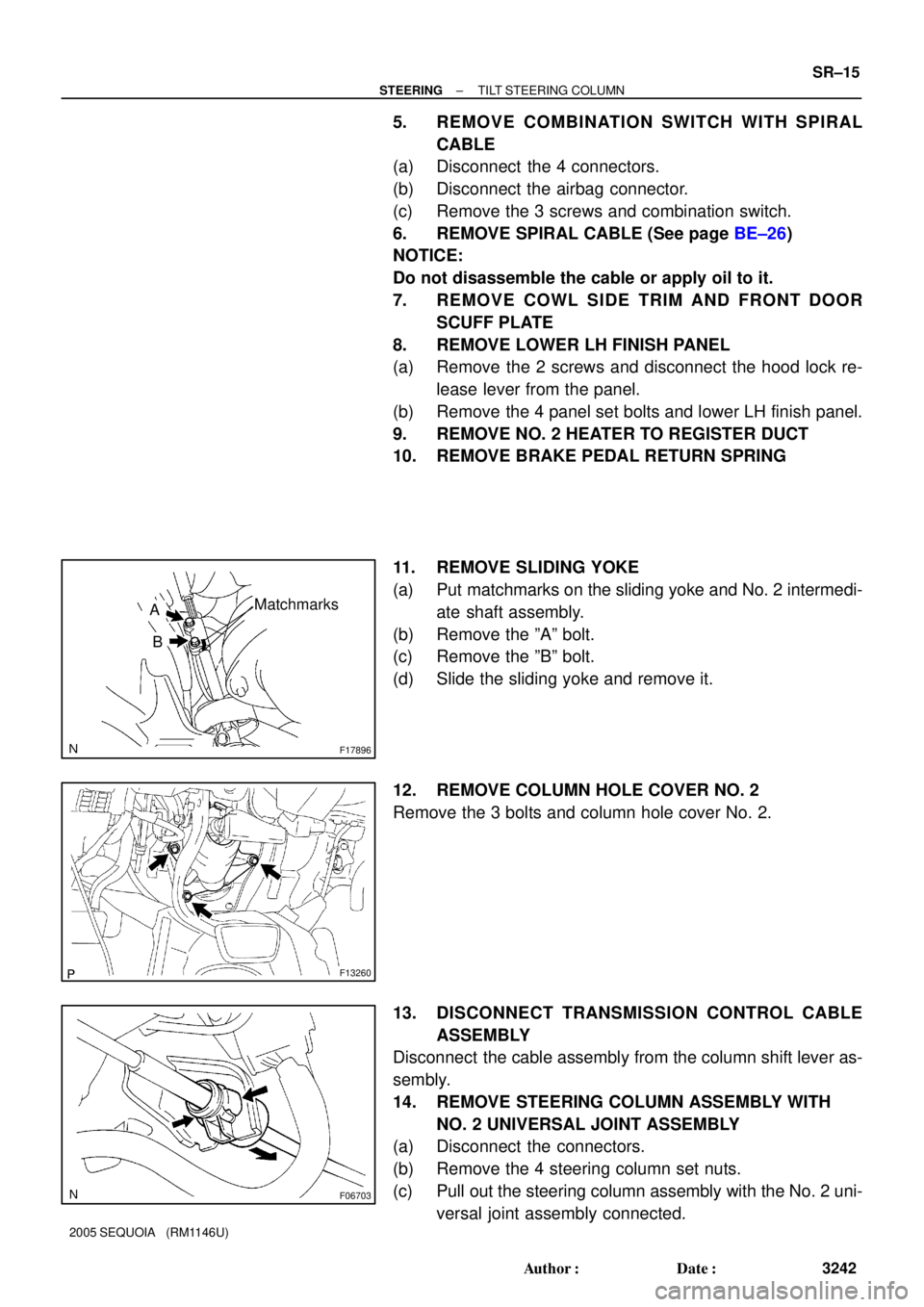
11. REMOVE SLIDING YOKE
(a) Put matchmarks on the sliding yoke and No. 2 intermedi-
ate shaft assembly.
(b) Remove the ºAº bolt.
(c) Remove the ºBº bolt.
(d) Slide the sliding yoke and remove it.
12. REMOVE COLUMN HOLE COVER NO. 2
Remove the 3 bolts and column hole cover No. 2.
13. DISCONNECT TRANSMISSION CONTROL CABLE
ASSEMBLY
Disconnect the cable assembly from the column shift lever as-
sembly.
14. REMOVE STEERING COLUMN ASSEMBLY WITH
NO. 2 UNIVERSAL JOINT ASSEMBLY
(a) Disconnect the connectors.
(b) Remove the 4 steering column set nuts.
(c) Pull out the steering column assembly with the No. 2 uni-
versal joint assembly connected.
Page 3259 of 4323
F13260
F17896
BMatchmarks
A
F19948
Mark
SR±24
± STEERINGTILT STEERING COLUMN
3251 Author�: Date�:
2005 SEQUOIA (RM1146U)
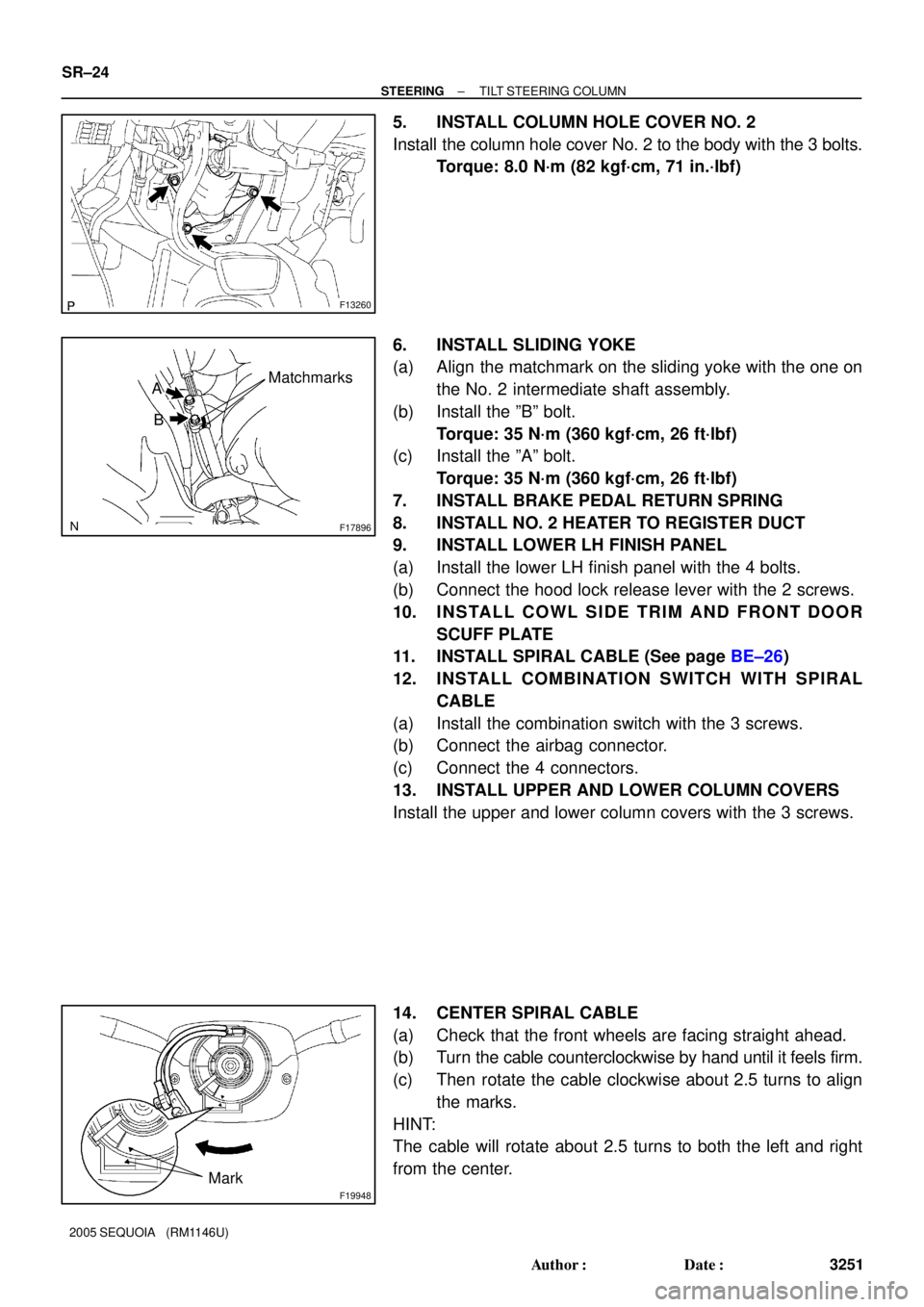
5. INSTALL COLUMN HOLE COVER NO. 2
Install the column hole cover No. 2 to the body with the 3 bolts.
Torque: 8.0 N´m (82 kgf´cm, 71 in.´lbf)
6. INSTALL SLIDING YOKE
(a) Align the matchmark on the sliding yoke with the one on
the No. 2 intermediate shaft assembly.
(b) Install the ºBº bolt.
Torque: 35 N´m (360 kgf´cm, 26 ft´lbf)
(c) Install the ºAº bolt.
Torque: 35 N´m (360 kgf´cm, 26 ft´lbf)
7. INSTALL BRAKE PEDAL RETURN SPRING
8. INSTALL NO. 2 HEATER TO REGISTER DUCT
9. INSTALL LOWER LH FINISH PANEL
(a) Install the lower LH finish panel with the 4 bolts.
(b) Connect the hood lock release lever with the 2 screws.
10. INSTALL COWL SIDE TRIM AND FRONT DOOR
SCUFF PLATE
11. INSTALL SPIRAL CABLE (See page BE±26)
12. INSTALL COMBINATION SWITCH WITH SPIRAL
CABLE
(a) Install the combination switch with the 3 screws.
(b) Connect the airbag connector.
(c) Connect the 4 connectors.
13. INSTALL UPPER AND LOWER COLUMN COVERS
Install the upper and lower column covers with the 3 screws.
14. CENTER SPIRAL CABLE
(a) Check that the front wheels are facing straight ahead.
(b) Turn the cable counterclockwise by hand until it feels firm.
(c) Then rotate the cable clockwise about 2.5 turns to align
the marks.
HINT:
The cable will rotate about 2.5 turns to both the left and right
from the center.
Page 3316 of 4323

R13455
10 m (33 ft) or more
SSTBattery
± SUPPLEMENTAL RESTRAINT SYSTEMSTEERING WHEEL PAD AND SPIRAL CABLE
RS±25
3308 Author�: Date�:
2005 SEQUOIA (RM1146U)
(2) Connect the SST connector to the airbag connector
of the spiral cable.
SST 09082±00700, 09082±00780
NOTICE:
To avoid damaging the SST connector and wire harness,
do not lock the secondary lock of the twin lock.
(3) Move the SST at least 10 m (33 ft) away from the ve-
hicle front side window.
(4) Maintaining enough clearance for the SST wire har-
ness in the front side window, close all doors and
windows of the vehicle.
NOTICE:
Take care not to damage the SST wire harness.
(5) Connect the red clip of the SST to the battery posi-
tive (+) terminal and the black clip of the SST to the
negative (±) terminal.
(f) Deploy the airbag.
(1) Check that no one is inside the vehicle or within a
10 m (33 ft) radius of the vehicle.
(2) Press the SST activation switch and deploy the air-
bag.
CAUTION:
�When deploying the airbag, make sure that no one is
near the vehicle.
�The steering wheel pad becomes extremely hot when
the airbag is deployed, so do not touch it for at least
30 minutes after deployment.
�Use gloves and safety glasses when handling a steer-
ing wheel pad with a deployed airbag.
�Do not apply water, etc. to a steering wheel pad with
a deployed airbag.
�Always wash your hands with water after completing
the operation.
2. DEPLOYMENT WHEN DISPOSING OF STEERING
WHEEL PAD ONLY
NOTICE:
�When disposing of the steering wheel pad, never use
the customer's vehicle to deploy the airbag.
�Be sure to follow the procedure given below when de-
ploying the airbag.
HINT:
Prepare a battery as the power source to deploy the airbag.
Page 3328 of 4323
AB0158
SSTBattery
H23215
H23216SST
R13455
10 m (33 ft) or more
SSTBattery
± SUPPLEMENTAL RESTRAINT SYSTEMFRONT PASSENGER AIRBAG ASSEMBLY
RS±37
3320 Author�: Date�:
2005 SEQUOIA (RM1146U)
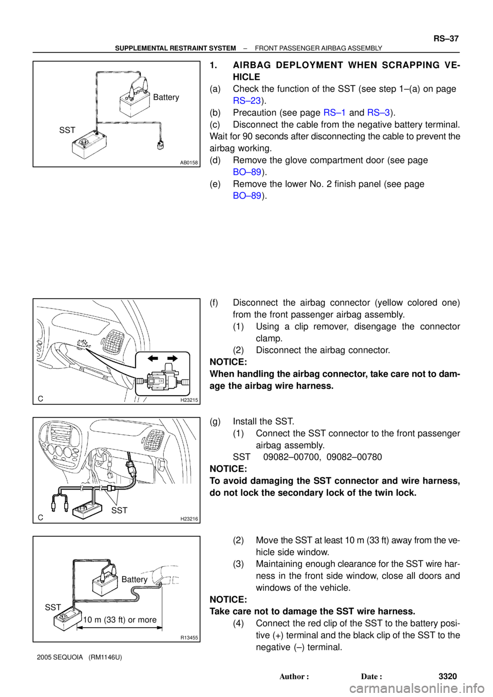
1. AIRBAG DEPLOYMENT WHEN SCRAPPING VE-
HICLE
(a) Check the function of the SST (see step 1±(a) on page
RS±23).
(b) Precaution (see page RS±1 and RS±3).
(c) Disconnect the cable from the negative battery terminal.
Wait for 90 seconds after disconnecting the cable to prevent the
airbag working.
(d) Remove the glove compartment door (see page
BO±89).
(e) Remove the lower No. 2 finish panel (see page
BO±89).
(f) Disconnect the airbag connector (yellow colored one)
from the front passenger airbag assembly.
(1) Using a clip remover, disengage the connector
clamp.
(2) Disconnect the airbag connector.
NOTICE:
When handling the airbag connector, take care not to dam-
age the airbag wire harness.
(g) Install the SST.
(1) Connect the SST connector to the front passenger
airbag assembly.
SST 09082±00700, 09082±00780
NOTICE:
To avoid damaging the SST connector and wire harness,
do not lock the secondary lock of the twin lock.
(2) Move the SST at least 10 m (33 ft) away from the ve-
hicle side window.
(3) Maintaining enough clearance for the SST wire har-
ness in the front side window, close all doors and
windows of the vehicle.
NOTICE:
Take care not to damage the SST wire harness.
(4) Connect the red clip of the SST to the battery posi-
tive (+) terminal and the black clip of the SST to the
negative (±) terminal.
Page 3342 of 4323
AB0158
Battery
SST
H17490
H17494SST SST
R13455
10 m (33 ft) or more
SSTBattery
± SUPPLEMENTAL RESTRAINT SYSTEMSIDE AIRBAG ASSEMBLY (Power Adjuster Type)
RS±51
3334 Author�: Date�:
2005 SEQUOIA (RM1146U)
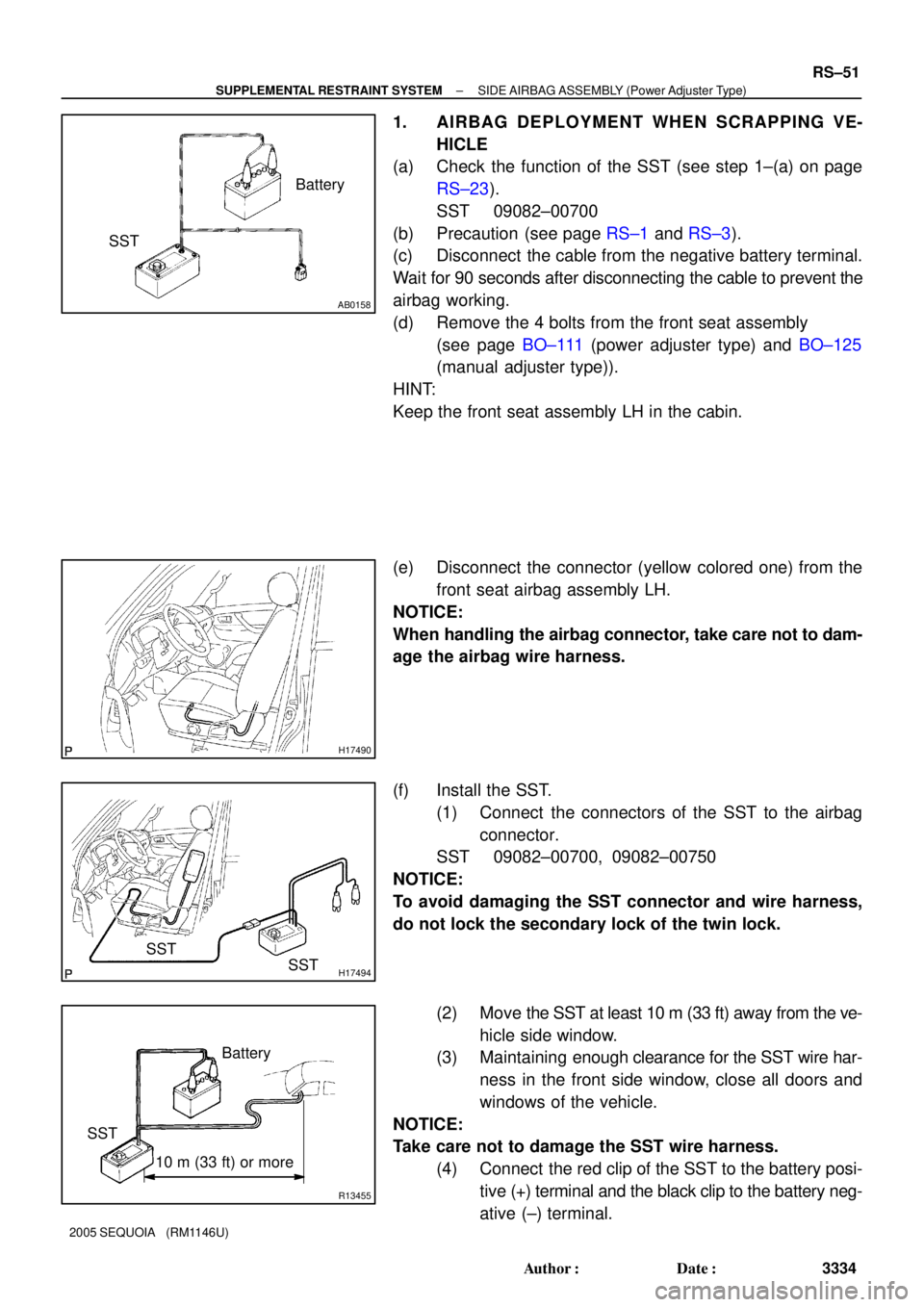
1. AIRBAG DEPLOYMENT WHEN SCRAPPING VE-
HICLE
(a) Check the function of the SST (see step 1±(a) on page
RS±23).
SST 09082±00700
(b) Precaution (see page RS±1 and RS±3).
(c) Disconnect the cable from the negative battery terminal.
Wait for 90 seconds after disconnecting the cable to prevent the
airbag working.
(d) Remove the 4 bolts from the front seat assembly
(see page BO±111 (power adjuster type) and BO±125
(manual adjuster type)).
HINT:
Keep the front seat assembly LH in the cabin.
(e) Disconnect the connector (yellow colored one) from the
front seat airbag assembly LH.
NOTICE:
When handling the airbag connector, take care not to dam-
age the airbag wire harness.
(f) Install the SST.
(1) Connect the connectors of the SST to the airbag
connector.
SST 09082±00700, 09082±00750
NOTICE:
To avoid damaging the SST connector and wire harness,
do not lock the secondary lock of the twin lock.
(2) Move the SST at least 10 m (33 ft) away from the ve-
hicle side window.
(3) Maintaining enough clearance for the SST wire har-
ness in the front side window, close all doors and
windows of the vehicle.
NOTICE:
Take care not to damage the SST wire harness.
(4) Connect the red clip of the SST to the battery posi-
tive (+) terminal and the black clip to the battery neg-
ative (±) terminal.
Page 3365 of 4323
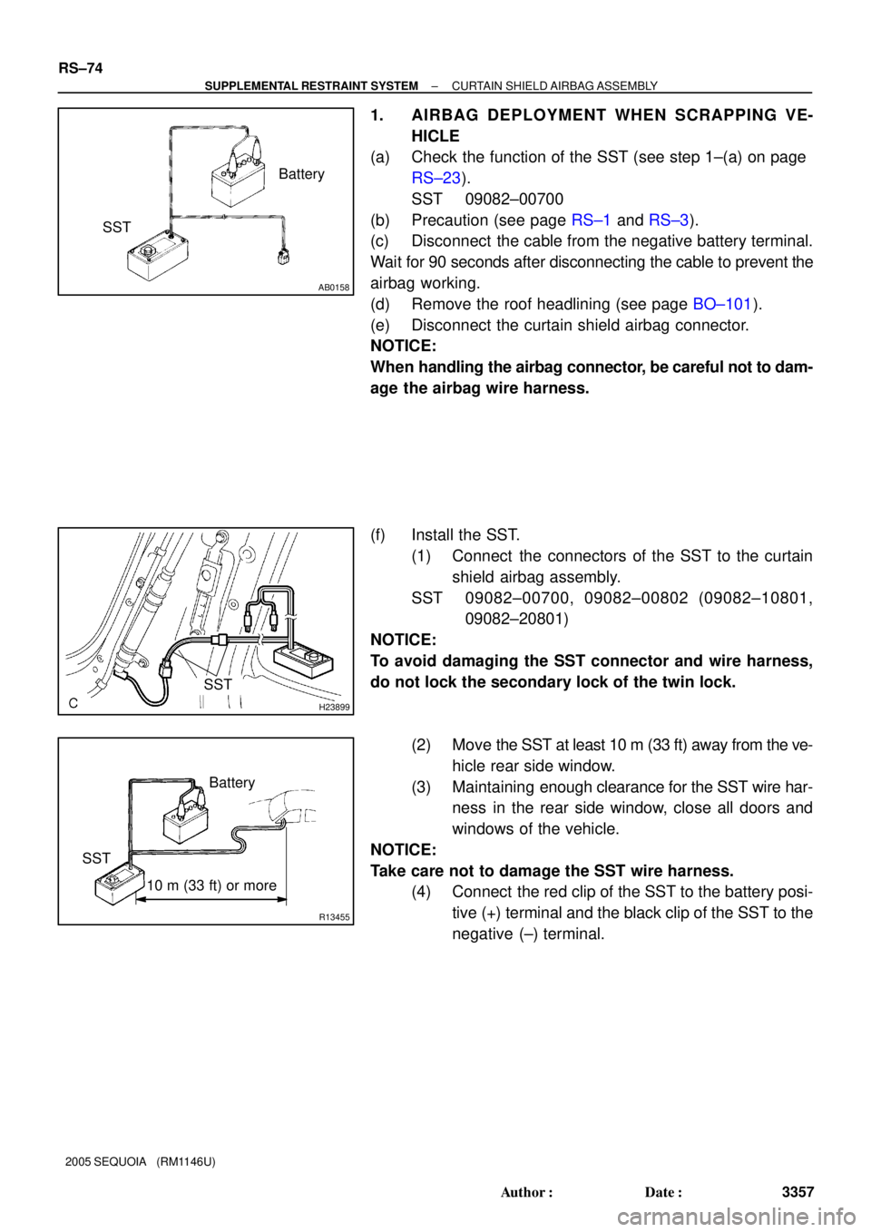
AB0158
Battery
SST
H23899
SST
R13455
10 m (33 ft) or more
SSTBattery RS±74
± SUPPLEMENTAL RESTRAINT SYSTEMCURTAIN SHIELD AIRBAG ASSEMBLY
3357 Author�: Date�:
2005 SEQUOIA (RM1146U)
1. AIRBAG DEPLOYMENT WHEN SCRAPPING VE-
HICLE
(a) Check the function of the SST (see step 1±(a) on page
RS±23).
SST 09082±00700
(b) Precaution (see page RS±1 and RS±3).
(c) Disconnect the cable from the negative battery terminal.
Wait for 90 seconds after disconnecting the cable to prevent the
airbag working.
(d) Remove the roof headlining (see page BO±101).
(e) Disconnect the curtain shield airbag connector.
NOTICE:
When handling the airbag connector, be careful not to dam-
age the airbag wire harness.
(f) Install the SST.
(1) Connect the connectors of the SST to the curtain
shield airbag assembly.
SST 09082±00700, 09082±00802 (09082±10801,
09082±20801)
NOTICE:
To avoid damaging the SST connector and wire harness,
do not lock the secondary lock of the twin lock.
(2) Move the SST at least 10 m (33 ft) away from the ve-
hicle rear side window.
(3) Maintaining enough clearance for the SST wire har-
ness in the rear side window, close all doors and
windows of the vehicle.
NOTICE:
Take care not to damage the SST wire harness.
(4) Connect the red clip of the SST to the battery posi-
tive (+) terminal and the black clip of the SST to the
negative (±) terminal.