Page 2618 of 4323
A23302
RH No.3 Timing Belt Cover
No.2 Timing
Belt Cover
LH No.3 Timing Belt Cover Drive Belt Idler Pulley
Camshaft Position
Sensor ConnectorCover Plate
Oil Cooler Pipe Engine Wire
7.5 (76, 66 in.´lbf)
16 (160, 12)
7.5 (76, 66 in.´lbf)
N´m (kgf´cm, ft´lbf) : Specified torque
Wire Grommet
39 (400, 29)
A23373
Timing BeltRH Camshaft Timing Pulley
LH Camshaft Timing Pulley
Timing Belt Tensioner
Fan BracketDust Boot
16 (160, 12)
32 (330, 24)
26 (270, 19)
N´m (kgf´cm, ft´lbf) : Specified torque
8.1 (83, 72 in.´lbf)
± ENGINE MECHANICALCYLINDER HEAD
EM±31
2610 Author�: Date�:
2005 SEQUOIA (RM1146U)
Page 2619 of 4323
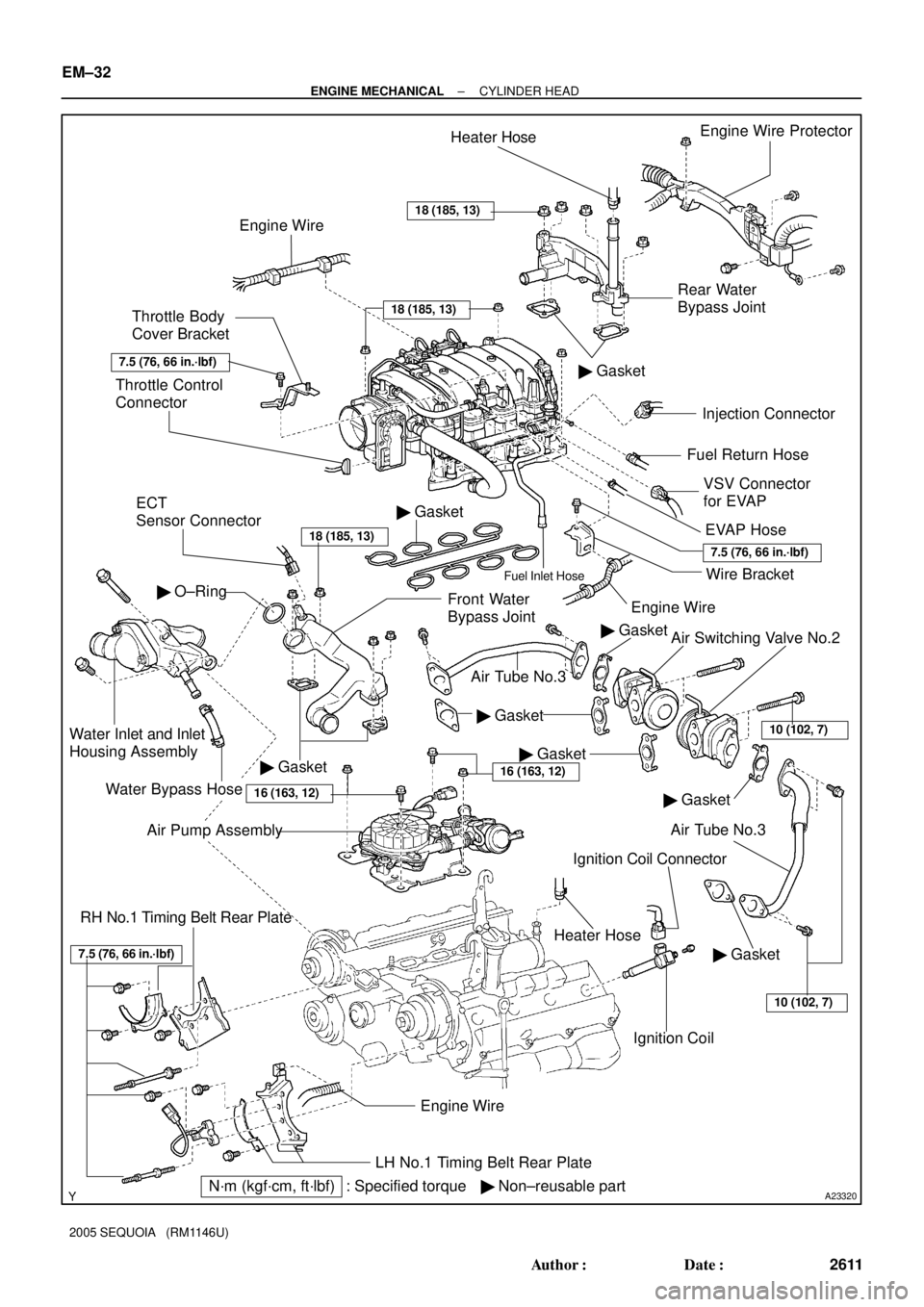
A23320
Rear Water
Bypass JointEngine Wire Protector
� Gasket
Injection Connector
Ignition Coil Connector
Ignition Coil Throttle Control
Connector
ECT
Sensor Connector
Front Water
Bypass Joint
Water Inlet and Inlet
Housing Assembly
Water Bypass Hose
LH No.1 Timing Belt Rear Plate
� Non±reusable partEngine Wire
� Gasket
� O±Ring
Engine WireHeater Hose
Throttle Body
Cover Bracket
VSV Connector
for EVAP Fuel Return Hose
Engine Wire
EVAP Hose
Heater Hose
Wire BracketFuel Inlet Hose
� Gasket
RH No.1 Timing Belt Rear Plate
� GasketAir Switching Valve No.2
Air Tube No.3
Air Tube No.3
� Gasket
N´m (kgf´cm, ft´lbf) : Specified torque� Gasket
18 (185, 13)
18 (185, 13)
18 (185, 13)
7.5 (76, 66 in.´lbf)
7.5 (76, 66 in.´lbf)
� Gasket
� Gasket
7.5 (76, 66 in.´lbf)
Air Pump Assembly
16 (163, 12)
10 (102, 7)
10 (102, 7)
16 (163, 12)
EM±32
± ENGINE MECHANICALCYLINDER HEAD
2611 Author�: Date�:
2005 SEQUOIA (RM1146U)
Page 2621 of 4323
 : Specified torque Camshaft Timing
Oil Control Valve
(Bank 2) Connector
RH Cylinder
Head Cover
Engine
Wire
Clamp
Bracket� Spark Plug Tube
Gasket")
A23322� Non±reusable part
N´m (kgf´cm, ft´lbf) : Specified torque Camshaft Timing
Oil Control Valve
(Bank 2) Connector
RH Cylinder
Head Cover
Engine
Wire
Clamp
Bracket� Spark Plug Tube
Gasket
Seal
Washer LH Cylinder
Head Cover
RH Intake
Camshaft
(with Timing
Tube)
Semi±circular Plug
Ground Strap
Ground WireEngine Wire
Clamp
x 9
Camshaft
Timing Oil
Control Valve
(Bank 1)
Camshaft Timing
Oil Control Valve
(Bank 2)
Front
Bearing Cap
Spark PlugGasket
Oil
Feed
Pipe
� Seal
Washer
Ground Wire
Camshaft Bearing Cap
16 (160, 12)� O±Ring
LH Exhaust
Camshaft
Camshaft
Housing Plug
Semi±circular
Plug
Strainer
� O±Ring
Gasket
�
LH Intake Camshaft
(with Timing Tube)
RH Exhaust
Camshaft
Camshaft
Housing
Plug
Engine Wire
Bracket
� LH Cylinder Head GasketLH Cylinder Head and
Exhaust Manifold Assembly
Air±fuel Ratio Sensor
(Bank 1 Sensor 1) Connector
RH Cylinder
Head Gasket
Engine
Wire
7.5 (76, 66 in.´lbf)
7.5 (76, 66 in.´lbf)
Seal
Washerx 9
x 10
�Camshaft Timing
Oil Control Valve
(Bank 1) Connector
Air±fuel Ratio Sensor
(Bank 2 Sensor 1)
Connector
Strainer
1st 40 (408, 30)
2nd Turn 90°
3rd
Turn 90° See page EM±60
Front
Bearing Cap
6.0 (600, 53 in.´lbf)
6.0 (600, 53 in.´lbf)
EM±34
± ENGINE MECHANICALCYLINDER HEAD
2613 Author�: Date�:
2005 SEQUOIA (RM1146U)
Page 2623 of 4323

REMOVAL
1. DRAIN ENGINE COOLANT
2. REMOVE THROTTLE BODY COVER
3. DISCONNECT TIMING BELT FROM CAM")
EM1X0±01
A02844
EM±36
± ENGINE MECHANICALCYLINDER HEAD
2615 Author�: Date�:
2005 SEQUOIA (RM1146U)
REMOVAL
1. DRAIN ENGINE COOLANT
2. REMOVE THROTTLE BODY COVER
3. DISCONNECT TIMING BELT FROM CAMSHAFT TIM-
ING PULLEYS (See page EM±16)
NOTICE:
�Be careful not to drop anything inside the timing belt
cover.
�Do not allow the belt to come into correct with oil, wa-
ter or dust.
4. REMOVE CAMSHAFT TIMING PULLEYS
(See page EM±16)
5. REMOVE CAMSHAFT POSITION SENSOR
(See page IG±8)
6. DISCONNECT PS PUMP FROM ENGINE
(See page EM±79)
7. REMOVE FRONT EXHAUST PIPE (See page EM±126)
8. REMOVE OIL DIPSTICK AND GUIDE FOR A/T
9. REMOVE IGNITION COILS (See page IG±5)
10. REMOVE TIMING BELT REAR PLATES
(a) Remove the 3 bolts, stud bolt and RH No.1 timing belt rear
plates.
(b) Disconnect the wire clamp from the LH timing belt rear
plate.
(c) Remove the 3 bolts, stud bolt and LH No.1 timing belt rear
plates.
11. DISCONNECT FUEL INLET HOSE (See page SF±27)
AND FUEL RETURN HOSE
12. DISCONNECT CONNECTORS FROM INTAKE MAN-
IFOLD
(a) Disconnect the throttle control connector.
(b) Disconnect the VSV connector for EVAP.
(c) Disconnect the 8 injector connectors.
(d) Disconnect the ECT sensor connector.
(e) Disconnect the 2 VSV connectors for the air injection sys-
tem.
(f) Disconnect the 8 ignition coil connectors.
(g) Disconnect the 2 air fuel ratio sensor connectors.
Page 2658 of 4323

(c) Install the")
A04015
Wire
Clamp
Bracket
A23333
Rear Water Bypass Joint
A23332
Front Water Bypass Joint
A23331
± ENGINE MECHANICALCYLINDER HEAD
EM±71
2650 Author�: Date�:
2005 SEQUOIA (RM1146U)
(c) Install the gasket to the cylinder head cover.
(d) Install the seal washer to the bolt.
(e) Install the cylinder head cover with the 9 bolts. Uniformly
tighten the bolts in several steps. Install the 2 cylinder
head covers.
Torque: 6.0 N´m (60 kgf´cm, 53 in.´lbf)
(f) Install the wire clamp bracket on the engine wire to the
camshaft bearing cap.
14. INSTALL ENGINE HANGERS
Torque: 37 N´m (380 kgf´cm, 27 ft´lbf)
15. INSTALL VVT SENSORS (See page SF±77)
16. INSTALL OIL DIPSTICK AND GUIDE FOR ENGINE
17. INSTALL OIL DIPSTICK AND GUIDE FOR A/T
18. INSTALL IGNITION COILS (See page IG±6)
19. INSTALL REAR WATER BYPASS JOINT
(a) Install 2 new gaskets to the cylinder head.
(b) Install the the water bypass joint with the 4 nuts to the cyl-
inder heads. Alternately tighten the nuts.
Torque: 18 N´m (185 kgf´cm, 13 ft´lbf)
20. INSTALL NO.2 AIR SWITCHING VALVES
(See page EC±26)
21. INSTALL AIR PUMP ASSEMBLY (See page EC±26)
22. INSTALL FRONT WATER BYPASS JOINT
Install 2 new gaskets and the water bypass joint with the 4 nuts.
Alternately tighten the nuts.
Torque: 18 N´m (185 kgf´cm, 13 ft´lbf)
23. INSTALL WATER INLET AND INLET HOUSING AS-
SEMBLY (See page CO±8)
24. ASSEMBLE INTAKE MANIFOLDS
(a) Install the 2 delivery pipes and 8 injectors (see page
SF±31).
(b) Install 2 new gaskets and fuel pulsation damper.
(c) Install a new O±ing and fuel pressure regulator with the
2 bolts.
(d) Install the fuel return pipe to the intake manifold with the
3 bolts.
(e) Connect the fuel return hose to the fuel pressure regula-
tor.
Page 2661 of 4323

(b)
(c)
(d)
EM±74
± ENGINE MECHANICALCYLINDER HEAD
2653 Author�: Date�:
2005 SEQUOIA (RM1146U)
26. CONNECT HOSES TO INTAKE MANIFOLD
(a) Connect the vacuum hose to the fuel pressure reg")
A23324
(a)
(b)
(c)
(d)
EM±74
± ENGINE MECHANICALCYLINDER HEAD
2653 Author�: Date�:
2005 SEQUOIA (RM1146U)
26. CONNECT HOSES TO INTAKE MANIFOLD
(a) Connect the vacuum hose to the fuel pressure regulator.
(b) Connect the PCV hose to the PCV valve on the LH the cyl-
inder head.
(c) Connect the EVAP hose (from charcoal canister) to the
VSV for EVAP.
(d) Connect the 2 vacuum hoses to the VSV for the air injec-
tion system.
(e) Connect the brake booster tube.
27. CONNECT CONNECTORS TO INTAKE MANIFOLD
(a) Connect the throttle control connector.
(b) Connect the 2 VSV connectors for the air injection sys-
tem.
(c) Connect the VSV connector for the EVAP.
(d) Connect the 8 injector connectors.
(e) Connect the ECT sensor connector.
(f) Connect the 2 air fuel ratio sensor connectors.
28. CONNECT FUEL INLET HOSE (See page SF±31) AND
FUEL RETURN HOSE
29. INSTALL TIMING BELT REAR PLATES
(a) Install the RH No.1 timing belt rear plates.
Install the RH No.1 timing belt rear plates to the cylinder
head with the 3 bolts and stud bolt.
Torque: 7.5 N´m (76 kgf´cm, 66 in.´lbf)
(b) Install the LH No.1 timing belt rear plates.
(1) Connect the wire clamp to the No.1 timing belt rear
plate.
(2) Install the LH No.1 timing belt rear plates to the cyl-
inder head with the 3 bolts and stud bolt.
Torque: 7.5 N´m (76 kgf´cm, 66 in.´lbf)
30. INSTALL THROTTLE BODY COVER
31. INSTALL IGNITION COILS (See page IG±6)
32. INSTALL OIL DIPSTICK AND GUIDE FOR A/T
33. INSTALL FRONT EXHAUST PIPE (See page EM±126)
34. INSTALL PS PUMP (See page EM±83)
35. INSTALL CAMSHAFT POSITION SENSOR
(See page IG±9)
36. INSTALL CAMSHAFT TIMING PULLEYS
(See page EM±23)
37. CONNECT TIMING BELT TO CAMSHAFT TIMING PUL-
LEYS (See page EM±23)
38. CHECK ENGINE OIL LEVEL
Page 2686 of 4323
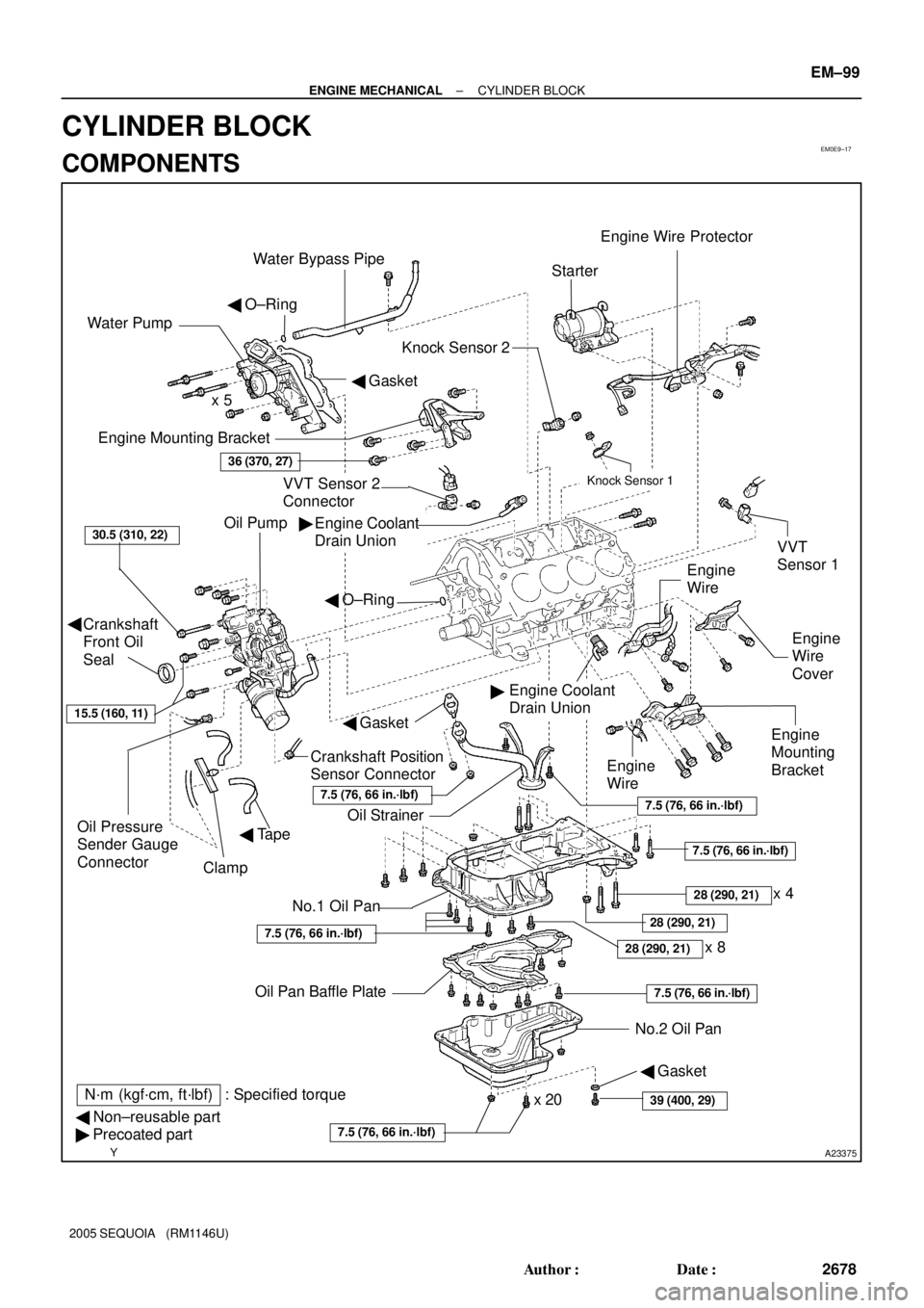
EM0E9±17
A23375
Engine Mounting Bracket
Oil Pump
Crankshaft
Front Oil
Seal
Crankshaft Position
Sensor Connector
No.1 Oil Pan
� Non±reusable part
� Precoated partOil StrainerEngine
Mounting
Bracket
VVT Sensor 2
ConnectorKnock Sensor 1
Knock Sensor 2
Engine Coolant
Drain UnionStarter
No.2 Oil Pan Oil Pan Baffle Platex 8 Water Pump
� Gasket � O±Ring
Engine
Wire
Engine
Wire
Cover VVT
Sensor 1
Engine Coolant
Drain Union
36 (370, 27)
30.5 (310, 22)
x 5
Oil Pressure
Sender Gauge
Connector
7.5 (76, 66 in.´lbf)
7.5 (76, 66 in.´lbf)
7.5 (76, 66 in.´lbf)
N´m (kgf´cm, ft´lbf) : Specified torque �
�
x 20
Clamp
Engine Wire Protector
� Tape
28 (290, 21)
7.5 (76, 66 in.´lbf)
28 (290, 21)
Water Bypass Pipe
7.5 (76, 66 in.´lbf)
� O±Ring
� Gasket
Engine
Wire
15.5 (160, 11)
39 (400, 29)
� Gasket
�
28 (290, 21)
7.5 (76, 66 in.´lbf)
x 4
± ENGINE MECHANICALCYLINDER BLOCK
EM±99
2678 Author�: Date�:
2005 SEQUOIA (RM1146U)
CYLINDER BLOCK
COMPONENTS
Page 2688 of 4323

DISASSEMBLY
1. INSTALL ENGINE TO ENGINE STAND
2. REMOVE")
EM122±05
A05112
Pull
Wire
Clamp
O±Ring
A08472
LH Side
± ENGINE MECHANICALCYLINDER BLOCK
EM±101
2680 Author�: Date�:
2005 SEQUOIA (RM1146U)
DISASSEMBLY
1. INSTALL ENGINE TO ENGINE STAND
2. REMOVE TIMING BELT AND PULLEYS
(See page EM±16)
3. REMOVE CYLINDER HEAD (See page EM±36)
4. REMOVE WATER BYPASS PIPE
(a) Disconnect the wire clamp (for knock sensor 1, 2) from
bracket of the water bypass pipe.
(b) Remove the bolt.
(c) Pull out the water bypass pipe from the water pump.
(d) Remove the O±ring from the water bypass pipe.
5. REMOVE STARTER (See page ST±5)
6. REMOVE KNOCK SENSORS (See page SF±66)
7. REMOVE VVT SENSORS (See page SF±77)
8. DISCONNECT ENGINE WIRE FROM LH SIDE OF CYL-
INDER BLOCK
(a) Remove the 2 bolts and engine wire cover from the LH
side of the cylinder block.
(b) Remove the 2 bolts, disconnect the brackets on the en-
gine wire from the cylinder block and engine mounting
bracket.
9. REMOVE OIL COOLER PIPE BRACKET FOR A/T
Remove the bolt and bracket.
10. REMOVE ENGINE MOUNTING BRACKETS
Remove the 4 bolts and mounting bracket. Remove the 2
mounting brackets.
11. REMOVE WATER PUMP (See page CO±6)
12. REMOVE NO.2 OIL PAN (See page LU±8)
13. REMOVE OIL PAN BAFFLE PLATE
14. REMOVE NO.1 OIL PAN (See page LU±8)
15. REMOVE OIL STRAINER
16. REMOVE OIL PUMP (See page LU±8)
17. REMOVE ENGINE COOLANT DRAIN UNIONS
Remove the 2 drain unions.