Page 2572 of 4323
I21123
Integration Control
and Panel
10
3A16
I19SPD G±O 10
3DSub J/B No. 4
G±O 3
C5 Combination Meter DI±2370
± DIAGNOSTICSAIR CONDITIONING SYSTEM
2564 Author�: Date�:
2005 SEQUOIA (RM1146U)
Vehicle Speed Signal Circuit
CIRCUIT DESCRIPTION
The integration control and panel monitors the vehicle speed through signals sent from the speed sensor.
It uses these signals to receive the ambient temperature sensor signal.
WIRING DIAGRAM
DI3WE±18
Page 2583 of 4323
I28845
ECM
E5
E5G±BIntegration Control
and Panel
I22
ACT
AC1
8 25
24
L±W 2
21
5 MG CLT Relay
J3 J/C
15
IG4 C
C Engine Room J/B
2
2C4
2G
3
A3
A/C Magnetic Clutch
and Lock Sensor R±Y
IA1 LG±B5
4
Engine Room R/B No. 2
2 22 G±Y
MGC 5
I19 I22 ACT
AC1
IA5
R±Y1
L±W L±W
R±Y
L
L
± DIAGNOSTICSAIR CONDITIONING SYSTEM
DI±2381
2575 Author�: Date�:
2005 SEQUOIA (RM1146U)
Compressor Circuit
CIRCUIT DESCRIPTION
The integration control and panel outputs the magnetic clutch ON signal from terminal AC1 to the ECM.
When the ECM receives this signal, it sends a signal from terminal ACT and switches the A/C magnetic clutch
relay ON. This turns the A/C magnetic clutch on.
WIRING DIAGRAM
DIAA8±03
Page 2589 of 4323

EM±2
± ENGINE MECHANICALCO/HC
2581 Author�: Date�:
2005 SEQUOIA (RM1146U)
5. IMMEDIATELY CHECK CO/HC CONCENTRATION AT
IDLE AND/OR 2,500 RPM
HINT:
When performing the 2 mode (2,500 rpm and idle) test, follow
the measurement orders are prescribed by the applicable local
regulations.
If the CO/HC concentration does not comply with regulations,
perform troubleshooting in the order given below.
(a) Check the air±fuel ratio sensors and heated oxygen sen-
sors operation.(See page DI±88 and DI±93)
(b) See the table below for possible causes, and then inspect
and correct the applicable causes if necessary.
COHCProblemsCauses
NormalHighRough idle7. Faulty ignitions:
�Incorrect timing
�Fouled, shorted or improperly gapped plugs
8. Incorrect valve clearance
9. Leaky intake and exhaust valves
10.Leaky cylinders
LowHighRough idle
(fluctuating HC reading)1. Vacuum leaks:
�PCV hoses
�Intake manifold
�Throttle body
�Brake booster line
2. Lean mixture causing misfire
HighHighRough idle
(Black smoke from exhaust)1. Restricted air filter
2. Faulty SFI systems:
�Faulty pressure regulator
�Defective ECT sensor
�Faulty ECM
�Faulty injectors
�Faulty throttle position sensor
�Faulty MAF meter
Page 2601 of 4323
A23302
RH No.3 Timing Belt Cover
No.2 Timing
Belt Cover
LH No.3 Timing Belt Cover Drive Belt Idler Pulley
Camshaft Position
Sensor ConnectorCover Plate
Oil Cooler Pipe Engine Wire
7.5 (76, 66 in.´lbf)
16 (160, 12)
7.5 (76, 66 in.´lbf)
N´m (kgf´cm, ft´lbf) : Specified torque
Wire Grommet
39 (400, 29)
A23303
Timing BeltLH Camshaft Timing Pulley
Timing Belt Tensioner
Dust Boot
245 (2,500, 181)
16 (160, 12)
32 (330, 24)
RH Camshaft Timing Pulley
26 (270, 19)Fan Bracket
N´m (kgf´cm, ft´lbf) : Specified torque
8.1 (83, 72 in.´lbf)
EM±14
± ENGINE MECHANICALTIMING BELT
2593 Author�: Date�:
2005 SEQUOIA (RM1146U)
Page 2602 of 4323
A23304
Generator WireDrive Belt Tensioner
No.1 Timing Belt Cover Generator
Crankshaft Pulley
39 (400, 29)
No.1 Idler Pulley
Timing Belt
Plate Washer
Crankshaft Timing Pulley
Timing Belt Cover Spacer No.2 Idler Pulley
Timing Belt Guide
(Crankshaft Angle Sensor Plate)Gasket
34.5 (350, 25)
34.5 (350, 25)�
N´m (kgf´cm, ft´lbf) : Specified torque
� Precoated part
26 (265, 19)
39 (400, 29)
15.5 (158, 11)
± ENGINE MECHANICALTIMING BELT
EM±15
2594 Author�: Date�:
2005 SEQUOIA (RM1146U)
Page 2603 of 4323

EM1WX±01
A08934
A04329
A04331
EM±16
± ENGINE MECHANICALTIMING BELT
2595 Author�: Date�:
2005 SEQUOIA (RM1146U)
REMOVAL
1. REMOVE ENGINE UNDER COVER
2. DRAIN ENGINE COOLANT
3. REMOVE RADIATOR ASSEMBLY (See page CO±17)
4. REMOVE THROTTLE BODY COVER
5. REMOVE INTAKE AIR CONNECTOR ASSEMBLY
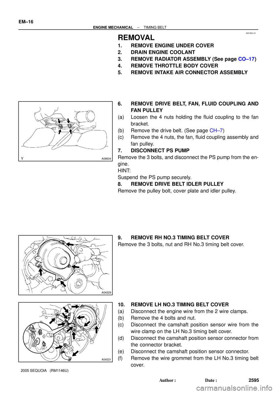
6. REMOVE DRIVE BELT, FAN, FLUID COUPLING AND
FAN PULLEY
(a) Loosen the 4 nuts holding the fluid coupling to the fan
bracket.
(b) Remove the drive belt. (See page CH±7)
(c) Remove the 4 nuts, the fan, fluid coupling assembly and
fan pulley.
7. DISCONNECT PS PUMP
Remove the 3 bolts, and disconnect the PS pump from the en-
gine.
HINT:
Suspend the PS pump securely.
8. REMOVE DRIVE BELT IDLER PULLEY
Remove the pulley bolt, cover plate and idler pulley.
9. REMOVE RH NO.3 TIMING BELT COVER
Remove the 3 bolts, nut and RH No.3 timing belt cover.
10. REMOVE LH NO.3 TIMING BELT COVER
(a) Disconnect the engine wire from the 2 wire clamps.
(b) Remove the 4 bolts and nut.
(c) Disconnect the camshaft position sensor wire from the
wire clamp on the LH No.3 timing belt cover.
(d) Disconnect the camshaft position sensor connector from
the connector bracket.
(e) Disconnect the camshaft position sensor connector.
(f) Remove the wire grommet from the LH No.3 timing belt
cover.
Page 2615 of 4323

A04331
A08934
EM±28
± ENGINE MECHANICALTIMING BELT
2607 Author�: Date�:
2005 SEQUOIA (RM1146U)
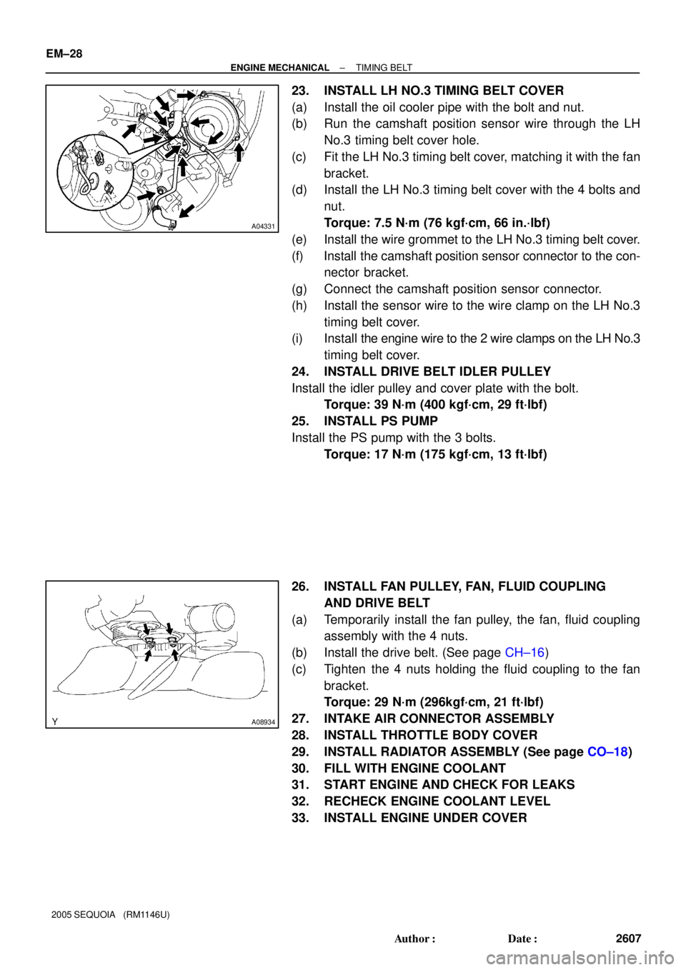
23. INSTALL LH NO.3 TIMING BELT COVER
(a) Install the oil cooler pipe with the bolt and nut.
(b) Run the camshaft position sensor wire through the LH
No.3 timing belt cover hole.
(c) Fit the LH No.3 timing belt cover, matching it with the fan
bracket.
(d) Install the LH No.3 timing belt cover with the 4 bolts and
nut.
Torque: 7.5 N´m (76 kgf´cm, 66 in.´lbf)
(e) Install the wire grommet to the LH No.3 timing belt cover.
(f) Install the camshaft position sensor connector to the con-
nector bracket.
(g) Connect the camshaft position sensor connector.
(h) Install the sensor wire to the wire clamp on the LH No.3
timing belt cover.
(i) Install the engine wire to the 2 wire clamps on the LH No.3
timing belt cover.
24. INSTALL DRIVE BELT IDLER PULLEY
Install the idler pulley and cover plate with the bolt.
Torque: 39 N´m (400 kgf´cm, 29 ft´lbf)
25. INSTALL PS PUMP
Install the PS pump with the 3 bolts.
Torque: 17 N´m (175 kgf´cm, 13 ft´lbf)
26. INSTALL FAN PULLEY, FAN, FLUID COUPLING
AND DRIVE BELT
(a) Temporarily install the fan pulley, the fan, fluid coupling
assembly with the 4 nuts.
(b) Install the drive belt. (See page CH±16)
(c) Tighten the 4 nuts holding the fluid coupling to the fan
bracket.
Torque: 29 N´m (296kgf´cm, 21 ft´lbf)
27. INTAKE AIR CONNECTOR ASSEMBLY
28. INSTALL THROTTLE BODY COVER
29. INSTALL RADIATOR ASSEMBLY (See page CO±18)
30. FILL WITH ENGINE COOLANT
31. START ENGINE AND CHECK FOR LEAKS
32. RECHECK ENGINE COOLANT LEVEL
33. INSTALL ENGINE UNDER COVER
Page 2617 of 4323
B17614
� GasketRH Front Exhaust Pipe
� Gasket
� Non±reusable part
N´m (kgf´cm, ft´lbf) : Specified torquePS Pump Oil Dipstick and
Guide for A/T
62 (632, 46)�Ring
�
� Gasket
17(175, 13)
62 (632, 46)
Heated Oxygen
Sensor
� Gasket
Heated Oxygen
Sensor
� O±Ring
EM±30
± ENGINE MECHANICALCYLINDER HEAD
2609 Author�: Date�:
2005 SEQUOIA (RM1146U)