Page 2712 of 4323

(b) Install the 2 drain unions.
Torque: 49 N")
A04856
FrontPort
A08472
LH Side
A05132
Push
Wire
Clamp
New
O±Ring
± ENGINE MECHANICALCYLINDER BLOCK
EM±125
2704 Author�: Date�:
2005 SEQUOIA (RM1146U)
(b) Install the 2 drain unions.
Torque: 49 N´m (500 kgf´cm, 36 ft´lbf)
HINT:
After applying the specified torque, rotate the drain union clock-
wise until its drain port is facing forward.
16. INSTALL OIL PUMP (See page LU±15)
17. INSTALL OIL STRAINER (See page LU±15)
18. INSTALL NO.1 OIL PAN (See page LU±15)
19. INSTALL OIL PAN BAFFLE PLATE
(See page LU±15)
20. INSTALL NO.2 OIL PAN (See page LU±15)
21. INSTALL WATER PUMP (See page CO±8)
22. INSTALL ENGINE MOUNTING BRACKETS
Install the mounting bracket with the 4 bolts. Install the 2 mount-
ing brackets.
Torque: 36 N´m (370 kgf´cm, 27 ft´lbf)
23. INSTALL ENGINE WIRE TO LH SIDE OF CYLINDER
BLOCK
(a) Install the brackets on the engine wire with the 2 bolts.
(b) Install the engine wire cover with the 2 bolts.
24. INSTALL OIL COOLER PIPE BRACKET FOR A/T
Install the bracket with the bolt.
25. INSTALL VVT SENSORS (See page SF±77)
26. INSTALL KNOCK SENSORS (See page SF±66)
27. INSTALL STARTER (See page ST±16)
28. INSTALL WATER BYPASS PIPE
(a) Install a new O±ring to the water bypass pipe.
(b) Apply soapy water to the O±ring.
(c) Push in the water bypass pipe end into the pipe hole of
the water pump.
(d) Install the water bypass pipe with the bolt.
Torque: 18 N´m (185 kgf´cm, 13 ft´lbf)
(e) Install the wire clamp to the bracket of the water bypass
pipe.
29. INSTALL CYLINDER HEADS (See page EM±60)
30. INSTALL TIMING BELT AND PULLEYS
(See page EM±23)
31. DISCONNECT ENGINE FROM ENGINE STAND
Page 2713 of 4323
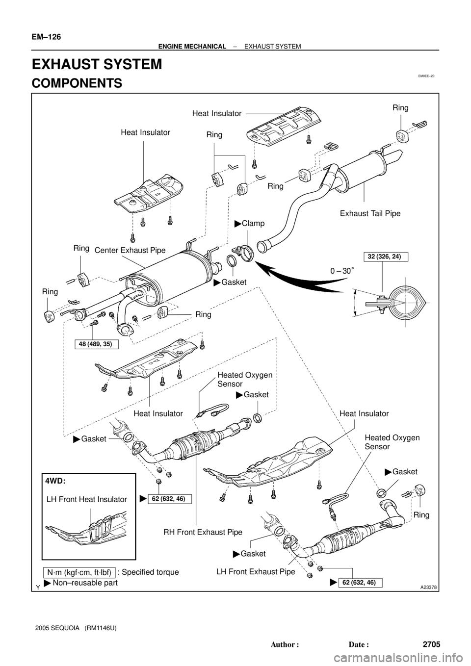
EM0EE±20
A23378
N´m (kgf´cm, ft´lbf): Specified torque
� Non±reusable partHeat Insulator
�
Ring
Ring
Clamp
Gasket Center Exhaust Pipe
Ring
Ring
�
Exhaust Tail Pipe
Ring
Heat Insulator
32 (326, 24)
0 ± 30°
Ring
48 (489, 35)
Heat Insulator
�Gasket
�Gasket
RH Front Exhaust Pipe
62 (632, 46)�
4WD:
LH Front Heat Insulator
Heated Oxygen
Sensor
Heat Insulator
Heated Oxygen
Sensor
�Gasket
Ring
62 (632, 46)�
LH Front Exhaust Pipe�Gasket
EM±126
± ENGINE MECHANICALEXHAUST SYSTEM
2705 Author�: Date�:
2005 SEQUOIA (RM1146U)
EXHAUST SYSTEM
COMPONENTS
Page 2714 of 4323
EM1X4±01
A23379
A23380
A23381
A23382
A23383
± ENGINE MECHANICALEXHAUST SYSTEM
EM±127
2706 Author�: Date�:
2005 SEQUOIA (RM1146U)
REMOVAL
1. REMOVE HEATED OXYGEN SENSORS
(a) Disconnect the heated oxygen sensor.
(b) Remove the heated oxygen sensor.
2. REMOVE RH AND LH FRONT EXHAUST PIPES
(a) Remove the 6 nuts and 2 gaskets, and disconnect the
front exhaust pipes from the exhaust manifold.
(b) Remove the 4 bolts, 2 gaskets and 2 front exhaust pipes
from the center exhaust pipe.
3. REMOVE CENTER EXHAUST PIPE
(a) Loosen the clamp bolt, disconnect the center exhaust
pipe and remove the gasket from the exhaust tail pipe.
(b) Remove the 5 rings and center exhaust pipe.
4. REMOVE EXHAUST TAIL PIPE
Remove the 2 rings and exhaust tail pipe.
5. REMOVE HEAT INSULATOR
(a) Remove the 5 bolts and No.1 heat insulator.
(b) Remove the 4 bolts and No.2 heat insulator.
(c) Remove the 3 bolts and No.3 heat insulator.
(d) Remove the 2 bolts and No.4 heat insulator.
Page 2716 of 4323
A23379
± ENGINE MECHANICALEXHAUST SYSTEM
EM±129
2708 Author�: Date�:
2005 SEQUOIA (RM1146U)
5. INSTALL HEATED OXYGEN SENSORS
(a) Install the heated oxygen sensor.
Torque: 44 N´m (450 kgf´cm, 33 ft´lbf)
(b) Connect the heated oxygen sensor connector.
Page 2719 of 4323
B17534
TWC
TWC
Air Pump Assembly
VSV for Secondary
Air Injection System
Air Switching Valve No.2
Pressure Sensor
Air Switching Valve
Air Injection Control Driver
± EMISSION CONTROLPARTS LAYOUT AND SCHEMATIC DRAWING
EC±3
2711 Author�: Date�:
2005 SEQUOIA (RM1146U)
Page 2720 of 4323
EC089±06
B17455
Charcoal
Canister
VSV for EVAP
Air Injection
Control DriverTWC EVAP
Service
PortPurge Line VENT Line
ECM Fuel Tank
Air Filter
ECM To Intake Manifold
Pump Module
M
P
Pressure
Sensor Pump MotorVent ValveRefueling Valve
Air Inlet Line
MP
Air Switching
Valve
Air Switching
Valve No.2
VSVs Air PumpPressure
Sensor
EVAPORATIVE EMISSION (EVAP) CONTROL SYSTEM
SECONDARY AIR INJECTION SYSTEM EC±4
± EMISSION CONTROLPARTS LAYOUT AND SCHEMATIC DRAWING
2712 Author�: Date�:
2005 SEQUOIA (RM1146U)
DRAWING
Page 2731 of 4323
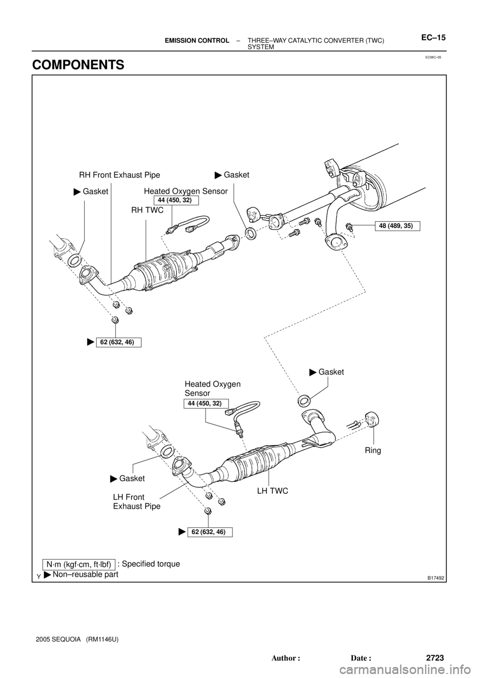
EC08C±05
B17492
N´m (kgf´cm, ft´lbf): Specified torque
� Non±reusable partRH Front Exhaust Pipe
RH TWC GasketHeated Oxygen Sensor
Ring
LH Front
Exhaust Pipe �
62 (632, 46)
Gasket �
�
Gasket �
Heated Oxygen
Sensor
Gasket �
LH TWC
62 (632, 46)�
48 (489, 35)
44 (450, 32)
44 (450, 32)
± EMISSION CONTROLTHREE±WAY CATALYTIC CONVERTER (TWC)
SYSTEMEC±15
2723 Author�: Date�:
2005 SEQUOIA (RM1146U)
COMPONENTS
Page 2732 of 4323
EC0NQ±01
A23379
A23380
A23381
EC±16± EMISSION CONTROLTHREE±WAY CATALYTIC CONVERTER (TWC)
SYSTEM
2724 Author�: Date�:
2005 SEQUOIA (RM1146U)
REPLACEMENT
1. DISCONNECT HEATED OXYGEN SENSORS
Remove the 2 heated oxygen sensors from the front exhaust
pipes.
2. REMOVE RH AND LH FRONT EXHAUST PIPES
(a) Remove the 6 nuts from the front side of the RH and LH
front exhaust pipes.
(b) Remove the 4 bolts from the rear side of the RH and LH
front exhaust pipes.
(c) Remove the RH and LH front exhaust pipes and 4 gas-
kets.
3. INSTALL RH AND LH FRONT EXHAUST PIPES
(a) Install 4 new gaskets to the RH and LH front exhaust
pipes.
(b) Install the 4 bolts.
Torque: 48 N´m (489 kgf´cm, 35 ft´lbf)
(c) Install 6 new nuts to the front side of the RH and LH front
exhaust pipes.
Torque: 62 N´m (632 kgf´cm, 46 ft´lbf)
4. INSTALL HEATED OXYGEN SENSOR
Install the 2 heated oxygen sensors to the RH and LH front ex-
haust pipes.
Torque: 44 N´m (450 kgf´cm, 32 ft´lbf)