Page 203 of 1943

J
FuseSystemPage
15AAM2
ABS
Engine Control
Hybrid Vehicle Immobiliser System
SRS
TOYOTA Hybrid System172
68
78
167
54
15ADOME
Combination Meter
Door Lock Control
Headlight (w/ Day")
2001 PRIUS (EWD414U)
J
FuseSystemPage
15AAM2
ABS
Engine Control
Hybrid Vehicle Immobiliser System
SRS
TOYOTA Hybrid System172
68
78
167
54
15ADOME
Combination Meter
Door Lock Control
Headlight (w/ Daytime Running Light)
Headlight (w//o Daytime Running Light)
Illumination
Interior Light
Key Reminder and Light Reminder Buzzer
Navigation System
Power Window
Radio and Player
Seat Belt Warning
Theft Deterrent
TOYOTA Hybrid System
Wireless Door Lock Control182
134
80
84
92
108
11 4
156
126
152
11 8
146
54
140
15AEFIEngine Control68
15ATHROEngine Control68
20AABS NO.3ABS172
20AHVTOYOTA Hybrid System54
30AABS NO.2ABS172
30ACDS FANRadiator Fan and Condenser Fan186
30AHEAD
Headlight (w/ Daytime Running Light)
Key Reminder and Light Reminder Buzzer
Light Auto Turn Off80
11 4
104
30ARDIRadiator Fan and Condenser Fan186
50AHTRAir Conditioning188
Instrument Panel J/B (See Page 30)
FuseSystemPage
5AECU±IG
ABS
Electric Tension Reducer
EMPS
Gateway System
Navigation System
Radiator Fan and Condenser Fan
Shift Lock172
162
164
160
156
186
132
5APANELIllumination92
7.5AECU±BAir Conditioning
Combination Meter188
182
*These are the page numbers of the first page on which the related system is shown.
Page 269 of 1943
NEW MODEL OUTLINE
INTERIOR
Easy-to-use luggage
compartment with ample space High point of vision for
easier understanding of
surrounding conditionsSpacious head clearance
for a more open feel
Ideal hip point height for easy access
182MO05
182MO06
Multi±Information Display
Meter
10
An interior which reflects the type of
comfort that will be regarded as a must in
cars hereinafter.
Package
The Prius package gives highest priority to driver and passenger
comfort.
�A spacious cab that is hard to imagine in a car of this size.
�Spacious head clearance for a more open feel.
�Ideal seat height for easy access.
�An easy-to-use luggage compartment with ample space.
Instrument Panel
The instrument panel is a balanced combination of functionality and
symmetry.
�Human-engineered layout perfectly suited to the new age, with centrally positioned operational functions.
Page 270 of 1943
NEW MODEL OUTLINE
(For U.S.A.)182MO07
Seat back pocket
(Driver's and
passenger's seat)
Driver's seat Passenger's seat
182MO08182MO09
A ± A Cross Section
Child seat
CRS lower anchorage
CRS anchor bracket
182MO10
A
A
Seat Back
Seat Cushion Child seat
11
Meter
A digital-display combination meter is located in the uppermost, center position of the instrument panel. This
ensures ease of visual confirmation, including that of all indicators.
Seat
[Front Seat]
�The pads fitted on the side of the seatback are of a different degrees of hardness, ensuring a superior hold.
�A seatback pocket has been included on the front seat providing additional and convenient storage space.
[Rear Seat]
�Three CRS anchor brackets that
FMVSS225-certified have been fitted on the
top section of the package tray trim to facili-
tate the mounting of child seats.
�An FMVSS225-certified child-seat CRS
lower anchorage is fitted on both outer-side
seats.
Page 277 of 1943

Glove box Accesory box Multi-box
Front door pocket
Seat back pocket
(Drivers and
passenger seat)
182MO24182MO09
182MO25
Small storage box
Cup hold")
NEW MODEL OUTLINE
MAIN EQUIPMENT
182MO23(For U.S.A.)
Glove box Accesory box Multi-box
Front door pocket
Seat back pocket
(Driver's and
passenger seat)
182MO24182MO09
182MO25
Small storage box
Cup holder
(for two caps use)11.839ft3 (by SAE suitcase method)
luggage space is secured.182MO26182MO27182MO28
18
Air Conditioning
An automatic air conditioning has been adopted
in consideration to ease of use.
�A clean air filter which removes pollen and
dust is included as a standard fitting for puri-
fying the air inside the cab.
�Two air conditioning modes, A/C for eco-
nomical air conditioning and MAX for espe-
cially strong air conditioning, are provided.
Wireless Door Lock Remote Control System
With the wireless door lock remote control system, all the doors can be locked and unlocked by signals emitted
by the transmitter.
Power Window System
A power window system which enables all windows to be raised or lowered with switches has been adopted.
An auto up/down function and jam protection function have been added to the driver's power window.
HV Immobiliser System
HV immobiliser system will not allow the HV system to be started by duplicate key is used. This system
will permit the HV system to be started only when the ID code of the transponder chip impregnated in the
key matches the ID code registered beforehand in the transponder key amplifier.
Theft Deterrent System
When an attempt is made to forcibly enter the vehicle or open the hood or trunk lid without a key, or when
the battery terminals are removed and reconnected, this system sounds the horn and flashes the headlights,
taillights and emergency flashers for about 1 minute to alert the owner. At the same time, it locks all the
doors.
Storage Space
Ample storage space with an emphasis on practicality provided throughout the Prius.
Instrument panel (passenger seat)Seat back pocketFront door pocket
Center console boxLuggage space
Page 391 of 1943

CHASSIS ± STEERING
182CH66
182CH67
Instrument Panel
Reinforcement
Main ShaftInstrument Panel
Reinforcement
Energy Absorbing Plate
Breakaway Bracket
DetachSecondary
Collision
Primary
CollisionContractDeform
After Collision
Before Collision129
�ENERGY ABSORBING MECHANISM
The energy absorbing mechanism in the steering column consists of a lower bracket, breakaway bracket, en-
ergy absorbing plate and a contractile main shaft. The steering column is mounted onto the instrument panel
reinforcement via a lower bracket and breakaway bracket which is supported via a capsule and energy absorb-
ing plate. The steering column and the steering gear box are connected with a contractile intermediate shaft.
Operational examples of this mechanism are follows.
When the steering gear box moves during a collision (primary collision), the main shaft and the intermediate
shaft contract, thus reduce the chance that the steering column and the steering wheel protrude into the cabin.
When an impact is transmitted to the steering wheel in a collision (secondary collision), the steering wheel
and the driver airbag help absorb the impact. In addition, the breakaway bracket and the lower bracket sepa-
rate, causing the entire steering column to move forward.
At this time, the energy absorbing plate becomes deformed to help absorb the impact of the secondary collision.
Page 393 of 1943
BODY ± BODY STRUCTURE
182BO02A ± A Cross Section B ± B Cross Section C ± C Cross SectionC
C(D) (E)
A
BB
A
131
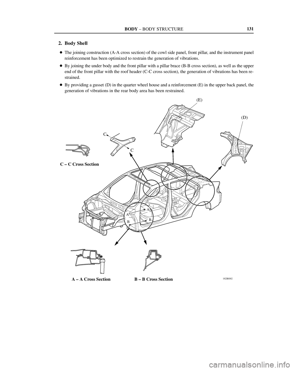
2. Body Shell
�The joining construction (A-A cross section) of the cowl side panel, front pillar, and the instrument panel
reinforcement has been optimized to restrain the generation of vibrations.
�By joining the under body and the front pillar with a pillar brace (B-B cross section), as well as the upper
end of the front pillar with the roof header (C-C cross section), the generation of vibrations has been re-
strained.
�By providing a gusset (D) in the quarter wheel house and a reinforcement (E) in the upper back panel, the
generation of vibrations in the rear body area has been restrained.
Page 428 of 1943
 Room Temperature Sensor
T")
BODY ELECTRICAL ± AIR CONDITIONING
182BE24Room Temperature
Sensor
182BE25
Evaporator Temperature
Sensor
182BE26
Solar Sensor
182BE27
Engine Coolant
Temperature Sensor 166
2) Room Temperature Sensor
The room temperature sensor has been pro-
vided inside the instrument finish lower panel.
The signals from this sensor are directly trans-
mitted to the air conditioning ECU.
3) Evaporator Temperature Sensor
The evaporator temperature sensor has been
provided behind the evaporator in the air
conditioning unit.
The signals from this sensor are directly trans-
mitted to the air conditioning ECU.
4) Solar Sensor
The solar sensor has been provided on top of
the instrument panel.
The signals from this sensor are directly trans-
mitted to the air conditioning ECU.
5) Engine Coolant Temperature Sensor
The water temperature sensor has been pro-
vided on the water outlet area on the left side
of the engine.
The signals from this sensor are transmitted to
the air conditioning ECU via the ECM.
Page 466 of 1943

2. PRECAUTIONS TO BE OBSERVED WHEN INSPECT-")
B04748
B04749
1. +Terminal
2. +Terminal3. ±Terminal
4. ±Terminal
B04750
± INTRODUCTIONFOR ALL OF VEHICLES
IN±13
13 Author�: Date�:
2001 PRIUS (RM778U)
2. PRECAUTIONS TO BE OBSERVED WHEN INSPECT-
ING OR SERVICING ENGINE COMPARTMENT
The PRIUS, automatically turns the engine ON and OFF when
the ignition switch is set to the ON position provided that the
READY light on the instrument panel is it.
Before inspecting or servicing the engine compartment, there-
fore, remove the ignition switch key.
3. ACTIONS TO BE TAKEN WHEN BATTERIES ARE DE-
PLETED
(a) Actions to be taken when the auxiliary battery is depleted
HINT:
The following phenomena indicate that the auxiliary battery is
depleted:
�No display appears on the instrument panel when you
turn the ignition switch to the ON position.
�The hybrid system does not start.
�The headlights are dark.
�The sound from the horn is weak.
NOTICE:
Never use a quick charger.
(1) Move the shift lever to the P position, and engage
the parking brake.
(2) Remove the ignition key plate from the ignition
switch.
(3) Using a booster cable, connect the 12 V battery of
the rescue vehicle and auxiliary battery of the
stalled vehicle, as shown in the illustration.
(4) Start the engine of the rescue vehicle and run the
engine at a speed slightly higher than the idling
speed for 5 minutes to charge the auxiliary battery
of the stalled vehicle.
(5) Turn the ignition switch of the stalled vehicle to the
START position to start the hybrid system.
If the hybrid system fails to start and the master and HV battery
warning lights come on, the HV battery may have been dis-
charged.
(6) Disconnect the booster cable in the reverse way of
the connection procedure.
NOTICE:
If the auxiliary battery needs to be replaced, replace it only
with a 12 V battery specially designed for the use of the
PRIUS.

182MO07
Seat back pocket
(Drivers and
passengers seat)
Drivers seat Passengers seat
182MO08182MO09
A ± A Cross Section
Child seat
CRS lower anchorage
CRS anchor brac")