Page 717 of 1943

A14055
BatteryEAN1
Noise
Filter Engine Room J/B
Ignition SW Instrument
Panel J/B3
B±R I4 Ignition Coil
and Igniter No. 4
1ECM
14
Y
E7
E7
E7
E7 13
12
25IGT4
IGT3
IGT2
IGF
E711
IGT1 1
2
4
G
W
B±R
B±R
Y±G 3
4
2 1I3 Ignition Coil
and Igniter No. 3
3
4
2 1I2 Ignition Coil
and Igniter No. 2
2 I1 Ignition Coil
and Igniter No. 1
1
3
4
B±W
B±W
B±W
B±W
B±W
B±W
B±RB±RB±R
B±R
W±B W±B
W±B
W±B
W±B
W±B
B±W
W±B B±W
W±R
B±W IG2 Relay
5
1 3
29
1J
3
1J 2
1A
3
1K
AM2
2
1B
B
F12
12G 11
2B 5
2C 22G 1
B±W
W±R
67
IG2AM2
FL
Block
No. 1
F13
1
B±G
FL
Block
No. 2
MAIN
W±B
A
AJ7
J/C
W±B
A
J1
J/C
IE
B±W
DI±116
± DIAGNOSTICSENGINE
2001 PRIUS (RM778U)
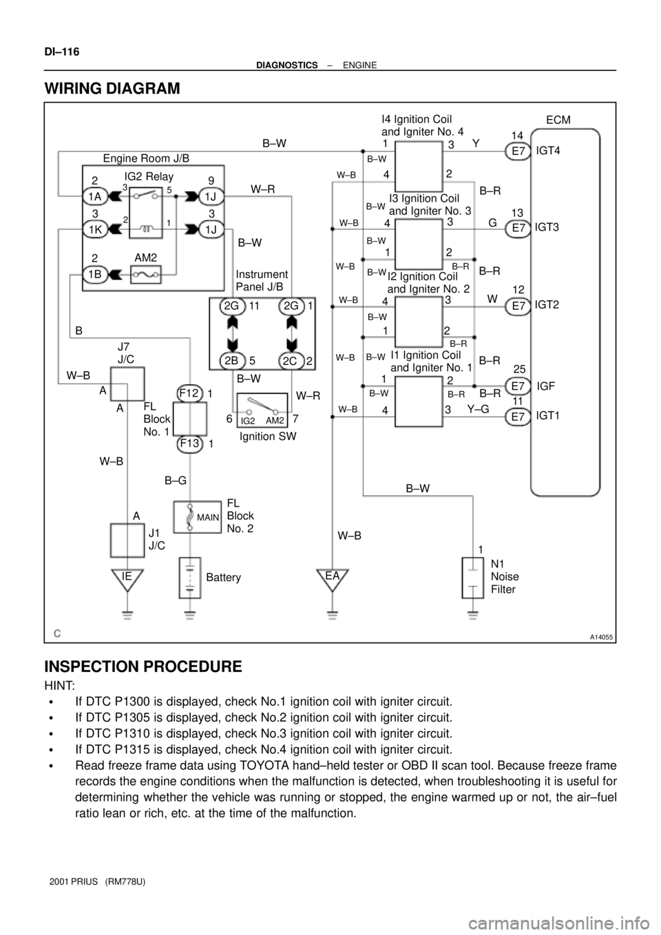
WIRING DIAGRAM
INSPECTION PROCEDURE
HINT:
�If DTC P1300 is displayed, check No.1 ignition coil with igniter circuit.
�If DTC P1305 is displayed, check No.2 ignition coil with igniter circuit.
�If DTC P1310 is displayed, check No.3 ignition coil with igniter circuit.
�If DTC P1315 is displayed, check No.4 ignition coil with igniter circuit.
�Read freeze frame data using TOYOTA hand±held tester or OBD II scan tool. Because freeze frame
records the engine conditions when the malfunction is detected, when troubleshooting it is useful for
determining whether the vehicle was running or stopped, the engine warmed up or not, the air±fuel
ratio lean or rich, etc. at the time of the malfunction.
Page 754 of 1943
A14058
ECM
+B 4
E8
BatteryW±RG±R
MREL 25 EFI Relay
I15 Ignition
SW EFI
IGSW 6
IE 1B35
AM2E9
J24 J25
J1
J/CE10 B
9 3
B
2C1 2
2G
24
A F121 3
1K 1F12 1A
1J 2
7 1
W±BW±R
B±W
B±G Engine Room J/B
F18
FL
Block
No. 2IA2
FL Block No. 19G±R
J7
J/C
B±W AM2 IG2
J/C Instrument
Panel J/B
F13 1
A
A W±BCB
MAIN
1 DI±156
± DIAGNOSTICSENGINE
2001 PRIUS (RM778U)
ECM Power Source Circuit
CIRCUIT INSPECTION
When the ignition switch is turned on, battery positive voltage is applied to IG2 Relay, terminal IGSW of the
ECM and the EFI main relay (Marking: EFI MAIN) control circuit in the ECM sends a signal to terminal MREL
of the ECM switching on the EFI main relay.
This signal causes current to flow to the coil, closing the contacts of the EFI main relay and supplying power
to terminals +B of the ECM.
If the ignition switch is turned off, the ECM continues to switch on the EFI main relay for a maximum of 2
seconds for the initial setting of the IAC valve.
WIRING DIAGRAM
DI7DK±02
Page 764 of 1943

A14037
Combination MeterECM
Instrument Panel J/B
W
BatteryE10 IG1 Relay
6
J11
J/C IG1C11
C10
ID DC/DCG±R
2A
A 5
W
W±B
F114
3GAUGE
Ignition SW 22
2 3B±Y
21
2 1
1 1
MAINL
AM1
B±G4
FL Block No. 1FL Block No. 2 F1312D
2B 2K 2H
86 5
AM1
W±G
MIL
DI±166
± DIAGNOSTICSENGINE
2001 PRIUS (RM778U)
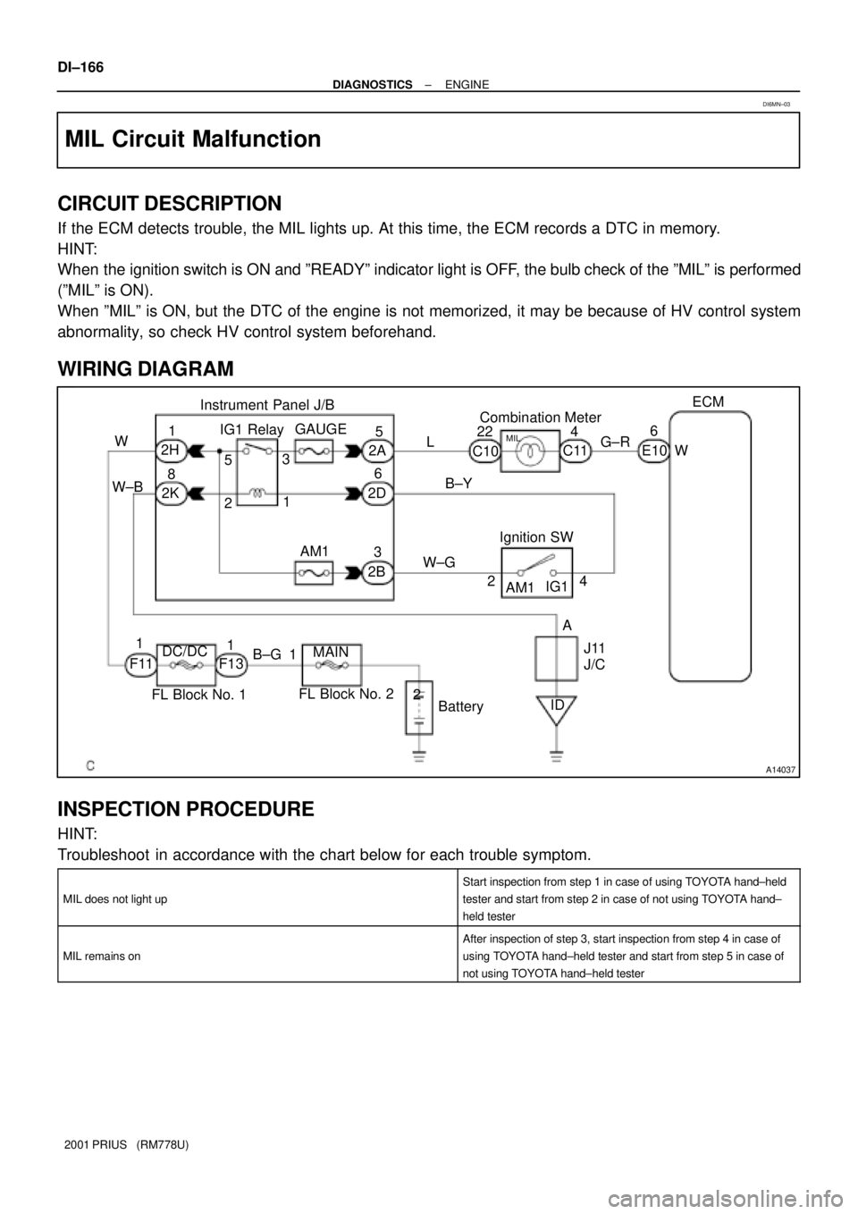
MIL Circuit Malfunction
CIRCUIT DESCRIPTION
If the ECM detects trouble, the MIL lights up. At this time, the ECM records a DTC in memory.
HINT:
When the ignition switch is ON and ºREADYº indicator light is OFF, the bulb check of the ºMILº is performed
(ºMILº is ON).
When ºMILº is ON, but the DTC of the engine is not memorized, it may be because of HV control system
abnormality, so check HV control system beforehand.
WIRING DIAGRAM
INSPECTION PROCEDURE
HINT:
Troubleshoot in accordance with the chart below for each trouble symptom.
MIL does not light up
Start inspection from step 1 in case of using TOYOTA hand±held
tester and start from step 2 in case of not using TOYOTA hand±
held tester
MIL remains on
After inspection of step 3, start inspection from step 4 in case of
using TOYOTA hand±held tester and start from step 5 in case of
not using TOYOTA hand±held tester
DI6MN±03
Page 767 of 1943
A14038
W±B 13TC E9
TC
CG D2 DLC3
4P±B
Instrument Panel J/B6 2
2K 2D ID1
AECM
ID W±BA J24
J/CE
W±BP±B
J11
J/C J26 J/C
P±B
A E
W±B 8 8P±BJ16 J/C
C
C
F08565
CG
(±)
(+) ON
TC
± DIAGNOSTICSENGINE
DI±169
2001 PRIUS (RM778U)
TC Terminal Circuit
CIRCUIT DESCRIPTION
Terminal TC and CG are located in the DLC3. When connecting these terminals, DTCs in normal mode or
test mode can be read through the MIL flashing in the combination meter.
WIRING DIAGRAM
INSPECTION PROCEDURE
HINT:
�Even though terminal TC is not connected with terminal CG, the MIL blinks.
�For the above phenomenon,an open or short in the wire harness, or malfunction inside the ECM is the
likely cause.
1 Check voltage between terminals TC and CG of DLC3.
PREPARATION:
Turn the ignition switch ON.
CHECK:
Measure the voltage between terminals TC and CG of the
DLC3.
OK:
Voltage: 9 ± 14 V
OK Check and replace ECM (See page IN±41).
NG
DI7DL±02
Page 810 of 1943
A14147
H14Hybrid Vehicle
Control ECU
H14
BatteryMAIN
B±G1 1
F1811 1
111
F13 2
3
2
2 Engine Room J/BSTP
ST1± G±W
J15 E
2 J14D J/C
G±W S3
Stop Light
SW
R±B
R±B4B±Y B±W B±W B
B
J24 J25 ID1J/C
B±W
I15
Ignition SW
W±RW±R
67
9
IG2AM2
Instrument Panel J/B
STOP 2C
2K2H 2G9
1J 1BAM2
B
W
F12 F11
DC/DC
Fusible Link Block No. 1 Fusible Link
Block No. 16
± DIAGNOSTICSHYBRID VEHICLE CONTROL SYSTEM
DI±215
2001 PRIUS (RM778U)
DTC P1520 Stop Light Switch (Cruise Control System)
Malfunction
CIRCUIT DESCRIPTION
The HV ECU detects the malfunction of the cruise control system and inhibits the operation of the cruise
control.
It detects faulty output of the STP and ST1± signals sent from the stop light switch or an error signal from
the brake ECU.
DTC P1520 ± Information code 115
INF. code.Detecting ConditionTrouble Area
11 5Open or short in stop light switch circuit
�Stop light switch
�Wire harness
�Brake ECU
WIRING DIAGRAM
DI82R±02
Page 826 of 1943
A14148
Hybrid Vehicle
Control ECU
Instrument Panel J/BI15
Ignition SW
Engine Room J/BFusible Link
Block No. 1ST2 R±W6
H13 2C2
W±R
2G2
W±R
1J9AM2
B
B±G
MAIN
Battery1B2
F121
F131
B±G
F181 Fusible Link
Block No. 2
ST2 AM27
8
± DIAGNOSTICSHYBRID VEHICLE CONTROL SYSTEM
DI±233
2001 PRIUS (RM778U)
CIRCUIT DESCRIPTION
The HV ECU checks the ST signal and detects malfunction. If the ST signal has +B short, the ST will always
be ON. Therefore, even with the IG ON when starting the THS, the system will start. To prevent this from
happening, the HV ECU detects the malfunction of the ST signal.
DTC P3100 ± Information code 142
INF. Code.Detecting ConditionTrouble Area
142When ST signal of HV ECU is ON, with ignition switch
turned OFF.�Wire harness
�HV ECU
�Ignition switch
WIRING DIAGRAM
Page 893 of 1943
A14736
BatteryMAINB±G 1
1
F18 1 1
5
1
F132 3 2
2Engine Room J/B
W±B IK1 2
14
5
AM2 B±WB±W
B±W I15
Ignition SW W±R
6 711
IG2 AM2
Instrument Panel J/B
2C
1K 1A 2G9
1J
1B
B
F12IG2 Relay
Fusible Link
Block No. 1
Fusible Link
Block No. 2 1J
2G
2BW±R
13 3
IE AA AB±W
2
W±B W±B
W±BW3
Water
Pump
Motor
J1
J/C J7
J/C W±B DI±302
± DIAGNOSTICSHYBRID VEHICLE CONTROL SYSTEM
2001 PRIUS (RM778U)
DTC P3130 Inverter Cooling System Malfunction
CIRCUIT DESCRIPTION
The HV ECU checks the operation of the inverter water pump and detects malfunction.
HINT:
�When using an OBD scan tool other than TOYOTA hand±held tester, check all the steps.
�When using TOYOTA hand±held tester, confirm the information code and check it.
DTC P3130 ± Information code 346
INF. code.Detecting ConditionTrouble Area
346Water pump system malfunction
�Inverter water pump
�IG2 relay
�Wire harness
WIRING DIAGRAM
DI839±02
Page 901 of 1943
A14138
2A C10
Combination
MeterHybrid Vehicle
Control ECU
L
H12 19
SPDI 68
IE1
13Instrument
Panel J/B
7
2BV±WJ/C
G
J27G
J28V±W V±W DI±310
± DIAGNOSTICSHYBRID VEHICLE CONTROL SYSTEM
2001 PRIUS (RM778U)
DTC P3145 Vehicle Speed Sensor Circuit Malfunction
CIRCUIT DESCRIPTION
DTC P3145 ± Information code 352
INF. code.Detecting ConditionTrouble Area
352No input of vehicle speed signal during cruise control driving�Wire harness
WIRING DIAGRAM
DI83C±02