2001 TOYOTA PRIUS instrument panel
[x] Cancel search: instrument panelPage 164 of 1943
2001 PRIUS (EWD414U)
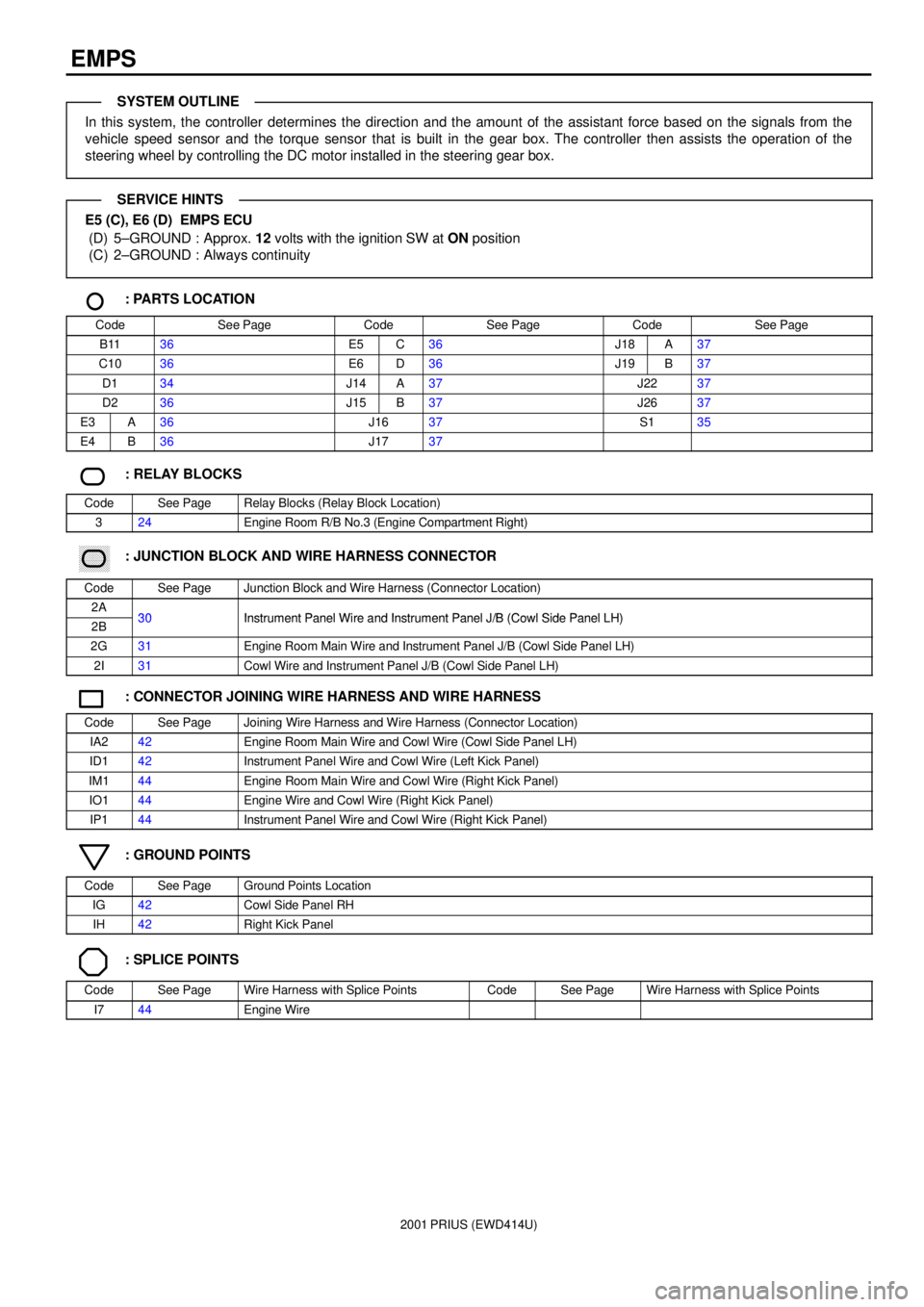
EMPS
In this system, the controller determines the direction and the amount of the assistant force based on the signals from the
vehicle speed sensor and the torque sensor that is built in the gear box. The controller then assists the operation of the
steering wheel by controlling the DC motor installed in the steering gear box.
E5 (C), E6 (D) EMPS ECU
(D) 5±GROUND : Approx. 12 volts with the ignition SW at ON position
(C) 2±GROUND : Always continuity
: PARTS LOCATION
CodeSee PageCodeSee PageCodeSee Page
B1136E5C36J18A37
C1036E6D36J19B37
D134J14A37J2237
D236J15B37J2637
E3A36J1637S135
E4B36J1737
: RELAY BLOCKS
CodeSee PageRelay Blocks (Relay Block Location)
324Engine Room R/B No.3 (Engine Compartment Right)
������ ���: JUNCTION BLOCK AND WIRE HARNESS CONNECTOR
CodeSee PageJunction Block and Wire Harness (Connector Location)
2A30Instrument Panel Wire and Instrument Panel J/B (Cowl Side Panel LH)2B30Instrument Panel Wire and Instrument Panel J/B (Cowl Side Panel LH)
2G31Engine Room Main Wire and Instrument Panel J/B (Cowl Side Panel LH)
2I31Cowl Wire and Instrument Panel J/B (Cowl Side Panel LH)
: CONNECTOR JOINING WIRE HARNESS AND WIRE HARNESS
CodeSee PageJoining Wire Harness and Wire Harness (Connector Location)
IA242Engine Room Main Wire and Cowl Wire (Cowl Side Panel LH)
ID142Instrument Panel Wire and Cowl Wire (Left Kick Panel)
IM144Engine Room Main Wire and Cowl Wire (Right Kick Panel)
IO144Engine Wire and Cowl Wire (Right Kick Panel)
IP144Instrument Panel Wire and Cowl Wire (Right Kick Panel)
: GROUND POINTS
CodeSee PageGround Points Location
IG42Cowl Side Panel RH
IH42Right Kick Panel
: SPLICE POINTS
CodeSee PageWire Harness with Splice PointsCodeSee PageWire Harness with Splice Points
I744Engine Wire
SYSTEM OUTLINE
SERVICE HINTS
Page 168 of 1943
2001 PRIUS (EWD414U)
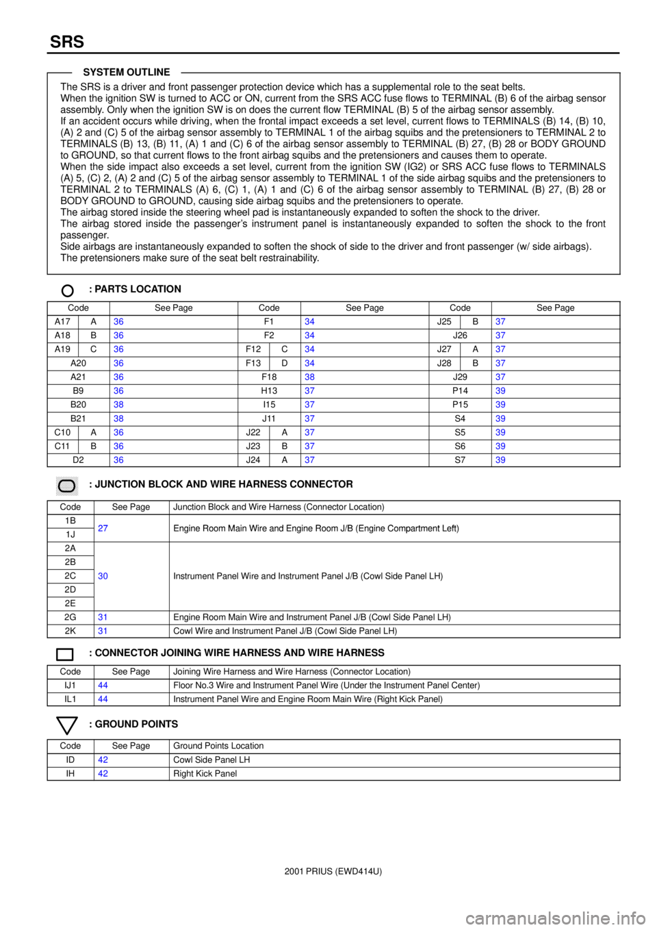
SRS
The SRS is a driver and front passenger protection device which has a supplemental role to the seat belts.
When the ignition SW is turned to ACC or ON, current from the SRS ACC fuse flows to TERMINAL (B) 6 of the airbag sensor
assembly. Only when the ignition SW is on does the current flow TERMINAL (B) 5 of the airbag sensor assembly.
If an accident occurs while driving, when the frontal impact exceeds a set level, current flows to TERMINALS (B) 14, (B) 10,
(A) 2 and (C) 5 of the airbag sensor assembly to TERMINAL 1 of the airbag squibs and the pretensioners to TERMINAL 2 to
TERMINALS (B) 13, (B) 11, (A) 1 and (C) 6 of the airbag sensor assembly to TERMINAL (B) 27, (B) 28 or BODY GROUND
to GROUND, so that current flows to the front airbag squibs and the pretensioners and causes them to operate.
When the side impact also exceeds a set level, current from the ignition SW (IG2) or SRS ACC fuse flows to TERMINALS
(A) 5, (C) 2, (A) 2 and (C) 5 of the airbag sensor assembly to TERMINAL 1 of the side airbag squibs and the pretensioners to
TERMINAL 2 to TERMINALS (A) 6, (C) 1, (A) 1 and (C) 6 of the airbag sensor assembly to TERMINAL (B) 27, (B) 28 or
BODY GROUND to GROUND, causing side airbag squibs and the pretensioners to operate.
The airbag stored inside the steering wheel pad is instantaneously expanded to soften the shock to the driver.
The airbag stored inside the passenger's instrument panel is instantaneously expanded to soften the shock to the front
passenger.
Side airbags are instantaneously expanded to soften the shock of side to the driver and front passenger (w/ side airbags).
The pretensioners make sure of the seat belt restrainability.
: PARTS LOCATION
CodeSee PageCodeSee PageCodeSee Page
A17A36F134J25B37
A18B36F234J2637
A19C36F12C34J27A37
A2036F13D34J28B37
A2136F1838J2937
B936H1337P1439
B2038I1537P1539
B2138J1137S439
C10A36J22A37S539
C11B36J23B37S639
D236J24A37S739
������ ���: JUNCTION BLOCK AND WIRE HARNESS CONNECTOR
CodeSee PageJunction Block and Wire Harness (Connector Location)
1B27Engine Room Main Wire and Engine Room J/B (Engine Compartment Left)1J27Engine Room Main Wire and Engine Room J/B (Engine Compartment Left)
2A
2B
2C30Instrument Panel Wire and Instrument Panel J/B (Cowl Side Panel LH)
2D
()
2E
2G31Engine Room Main Wire and Instrument Panel J/B (Cowl Side Panel LH)
2K31Cowl Wire and Instrument Panel J/B (Cowl Side Panel LH)
: CONNECTOR JOINING WIRE HARNESS AND WIRE HARNESS
CodeSee PageJoining Wire Harness and Wire Harness (Connector Location)
IJ144Floor No.3 Wire and Instrument Panel Wire (Under the Instrument Panel Center)
IL144Instrument Panel Wire and Engine Room Main Wire (Right Kick Panel)
: GROUND POINTS
CodeSee PageGround Points Location
ID42Cowl Side Panel LH
IH42Right Kick Panel
SYSTEM OUTLINE
Page 176 of 1943
2001 PRIUS (EWD414U)
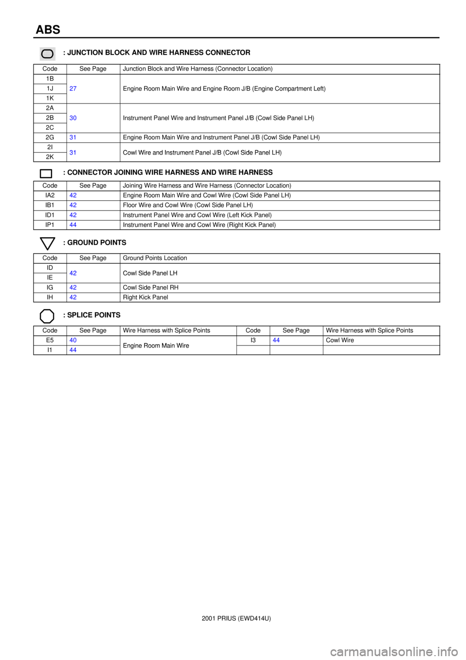
ABS
������ ���: JUNCTION BLOCK AND WIRE HARNESS CONNECTOR
CodeSee PageJunction Block and Wire Harness (Connector Location)
1B
1J27Engine Room Main Wire and Engine Room J/B (Engine Compartment Left)
1K
gg(g)
2A
2B30Instrument Panel Wire and Instrument Panel J/B (Cowl Side Panel LH)
2C
()
2G31Engine Room Main Wire and Instrument Panel J/B (Cowl Side Panel LH)
2I31Cowl Wire and Instrument Panel J/B (Cowl Side Panel LH)2K31Cowl Wire and Instrument Panel J/B (Cowl Side Panel LH)
: CONNECTOR JOINING WIRE HARNESS AND WIRE HARNESS
CodeSee PageJoining Wire Harness and Wire Harness (Connector Location)
IA242Engine Room Main Wire and Cowl Wire (Cowl Side Panel LH)
IB142Floor Wire and Cowl Wire (Cowl Side Panel LH)
ID142Instrument Panel Wire and Cowl Wire (Left Kick Panel)
IP144Instrument Panel Wire and Cowl Wire (Right Kick Panel)
: GROUND POINTS
CodeSee PageGround Points Location
ID42Cowl Side Panel LHIE42Cowl Side Panel LH
IG42Cowl Side Panel RH
IH42Right Kick Panel
: SPLICE POINTS
CodeSee PageWire Harness with Splice PointsCodeSee PageWire Harness with Splice Points
E540Engine Room Main WireI344Cowl Wire
I144Engine Room Main Wire
Page 179 of 1943
2001 PRIUS (EWD414U)
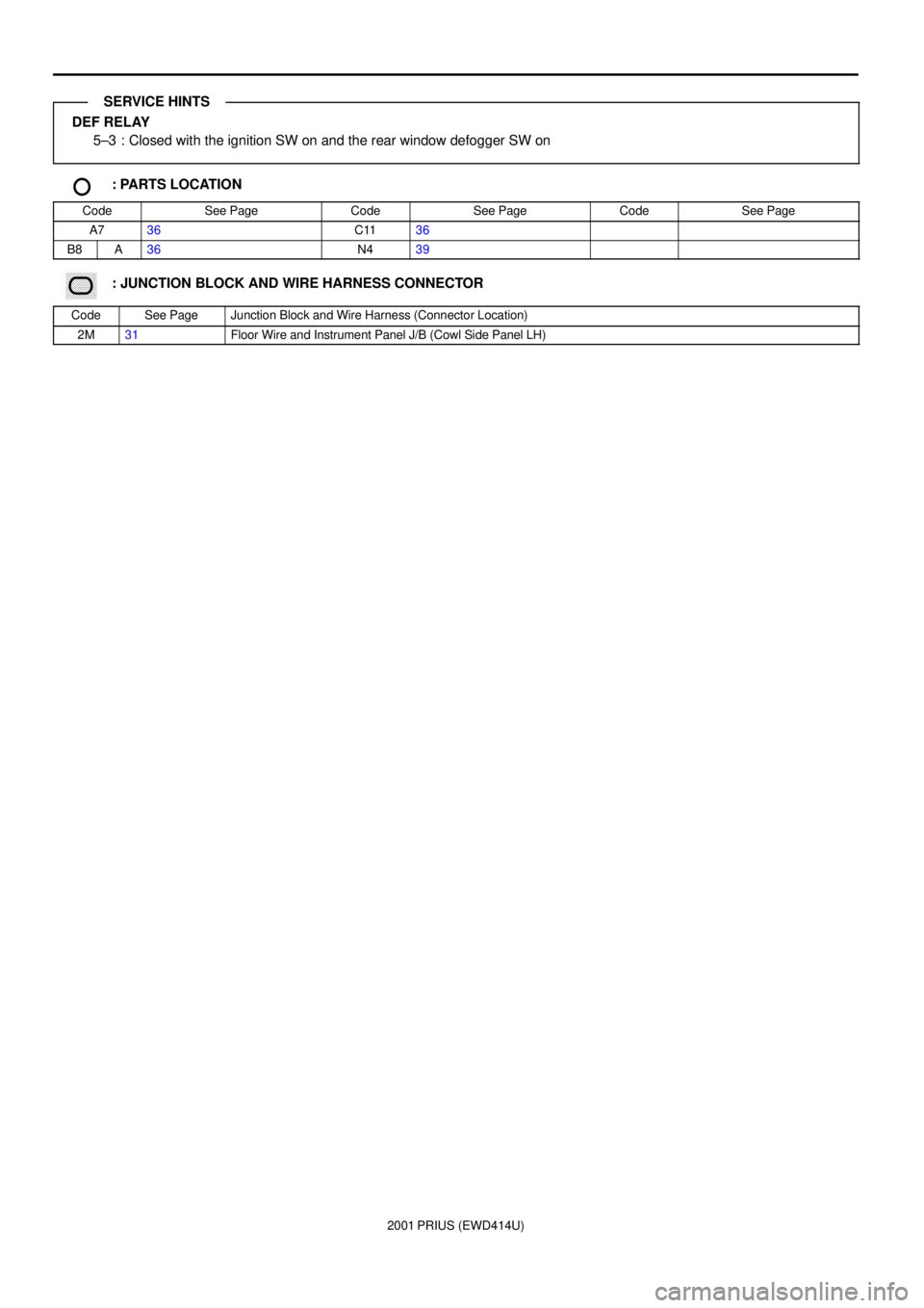
DEF RELAY
5±3 : Closed with the ignition SW on and the rear window defogger SW on
: PARTS LOCATION
CodeSee PageCodeSee PageCodeSee Page
A736C1136
B8A36N439
������ ���: JUNCTION BLOCK AND WIRE HARNESS CONNECTOR
CodeSee PageJunction Block and Wire Harness (Connector Location)
2M31Floor Wire and Instrument Panel J/B (Cowl Side Panel LH)
SERVICE HINTS
Page 183 of 1943
2001 PRIUS (EWD414U)
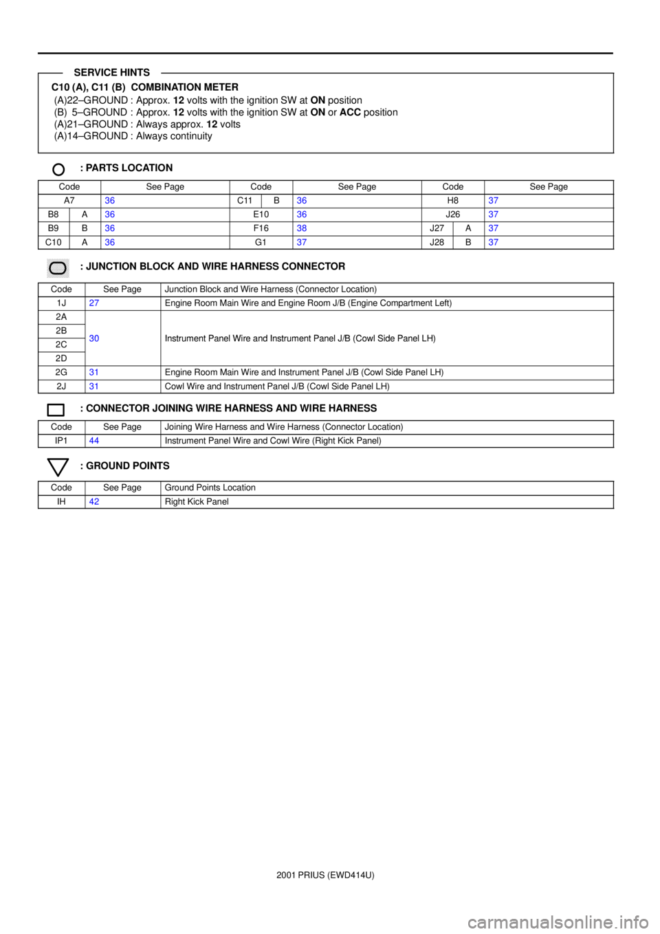
C10 (A), C11 (B) COMBINATION METER
(A)22±GROUND : Approx. 12 volts with the ignition SW at ON position
(B) 5±GROUND : Approx. 12 volts with the ignition SW at ON or ACC position
(A)21±GROUND : Always approx. 12 volts
(A)14±GROUND : Always continuity
: PARTS LOCATION
CodeSee PageCodeSee PageCodeSee Page
A736C11B36H837
B8A36E1036J2637
B9B36F1638J27A37
C10A36G137J28B37
������ ���: JUNCTION BLOCK AND WIRE HARNESS CONNECTOR
CodeSee PageJunction Block and Wire Harness (Connector Location)
1J27Engine Room Main Wire and Engine Room J/B (Engine Compartment Left)
2A
2B30Instrument Panel Wire and Instrument Panel J/B (Cowl Side Panel LH)2C30Instrument Panel Wire and Instrument Panel J/B (Cowl Side Panel LH)
2D
2G31Engine Room Main Wire and Instrument Panel J/B (Cowl Side Panel LH)
2J31Cowl Wire and Instrument Panel J/B (Cowl Side Panel LH)
: CONNECTOR JOINING WIRE HARNESS AND WIRE HARNESS
CodeSee PageJoining Wire Harness and Wire Harness (Connector Location)
IP144Instrument Panel Wire and Cowl Wire (Right Kick Panel)
: GROUND POINTS
CodeSee PageGround Points Location
IH42Right Kick Panel
SERVICE HINTS
Page 185 of 1943
2001 PRIUS (EWD414U)
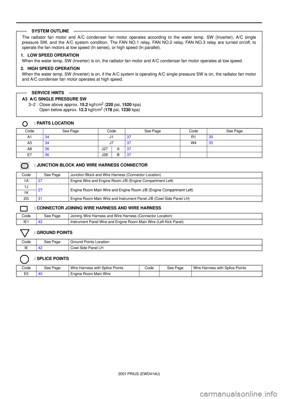
The radiator fan motor and A/C condenser fan motor operates according to the water temp. SW (Inverter), A/C single
pressure SW, and the A/C system condition. The FAN NO.1 relay, FAN NO.2 relay, FAN NO.3 relay are turned on/off, to
operate the fan motors at low speed (In series), or high speed (In parallel).
1. LOW SPEED OPERATION
When the water temp. SW (Inverter) is on, the radiator fan motor and A/C condenser fan motor operates at low speed.
2. HIGH SPEED OPERATION
When the water temp. SW (Inverter) is on, if the A/C system is operating A/C single pressure SW is on, the radiator fan motor
and A/C condenser fan motor operates at high speed.
A3 A/C SINGLE PRESSURE SW
3±2 : Close above approx. 15.2 kgf/cm2 (220 psi, 1520 kpa)
Open below approx. 12.3 kgf/cm2 (178 psi, 1230 kpa)
: PARTS LOCATION
CodeSee PageCodeSee PageCodeSee Page
A134J137R135
A334J737W435
A836J27A37
E736J28B37
������ ���: JUNCTION BLOCK AND WIRE HARNESS CONNECTOR
CodeSee PageJunction Block and Wire Harness (Connector Location)
1A27Engine Wire and Engine Room J/B (Engine Compartment Left)
1J27Engine Room Main Wire and Engine Room J/B (Engine Compartment Left)1K27Engine Room Main Wire and Engine Room J/B (Engine Compartment Left)
2G31Engine Room Main Wire and Instrument Panel J/B (Cowl Side Panel LH)
: CONNECTOR JOINING WIRE HARNESS AND WIRE HARNESS
CodeSee PageJoining Wire Harness and Wire Harness (Connector Location)
IE142Instrument Panel Wire and Engine Room Main Wire (Left Kick Panel)
: GROUND POINTS
CodeSee PageGround Points Location
IE42Cowl Side Panel LH
: SPLICE POINTS
CodeSee PageWire Harness with Splice PointsCodeSee PageWire Harness with Splice Points
E540Engine Room Main Wire
SYSTEM OUTLINE
SERVICE HINTS
Page 191 of 1943
2001 PRIUS (EWD414U)
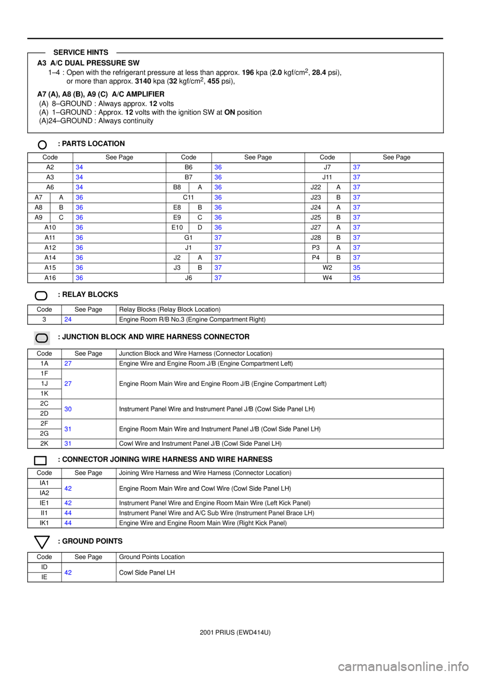
A3 A/C DUAL PRESSURE SW
1±4 : Open with the refrigerant pressure at less than approx. 196 kpa (2.0 kgf/cm2, 28.4 psi),
or more than approx. 3140 kpa (32 kgf/cm2, 455 psi),
A7 (A), A8 (B), A9 (C) A/C AMPLIFIER
(A) 8±GROUND : Always approx. 12 volts
(A) 1±GROUND : Approx. 12 volts with the ignition SW at ON position
(A)24±GROUND : Always continuity
: PARTS LOCATION
CodeSee PageCodeSee PageCodeSee Page
A234B636J737
A334B736J1137
A634B8A36J22A37
A7A36C1136J23B37
A8B36E8B36J24A37
A9C36E9C36J25B37
A1036E10D36J27A37
A1136G137J28B37
A1236J137P3A37
A1436J2A37P4B37
A1536J3B37W235
A1636J637W435
: RELAY BLOCKS
CodeSee PageRelay Blocks (Relay Block Location)
324Engine Room R/B No.3 (Engine Compartment Right)
������ ���: JUNCTION BLOCK AND WIRE HARNESS CONNECTOR
CodeSee PageJunction Block and Wire Harness (Connector Location)
1A27Engine Wire and Engine Room J/B (Engine Compartment Left)
1F
1J27Engine Room Main Wire and Engine Room J/B (Engine Compartment Left)
1K
gg(g)
2C30Instrument Panel Wire and Instrument Panel J/B (Cowl Side Panel LH)2D30Instrument Panel Wire and Instrument Panel J/B (Cowl Side Panel LH)
2F31Engine Room Main Wire and Instrument Panel J/B (Cowl Side Panel LH)2G31Engine Room Main Wire and Instrument Panel J/B (Cowl Side Panel LH)
2K31Cowl Wire and Instrument Panel J/B (Cowl Side Panel LH)
: CONNECTOR JOINING WIRE HARNESS AND WIRE HARNESS
CodeSee PageJoining Wire Harness and Wire Harness (Connector Location)
IA142Engine Room Main Wire and Cowl Wire (Cowl Side Panel LH)IA242Engine Room Main Wire and Cowl Wire (Cowl Side Panel LH)
IE142Instrument Panel Wire and Engine Room Main Wire (Left Kick Panel)
II144Instrument Panel Wire and A/C Sub Wire (Instrument Panel Brace LH)
IK144Engine Wire and Engine Room Main Wire (Right Kick Panel)
: GROUND POINTS
CodeSee PageGround Points Location
ID42Cowl Side Panel LHIE42Cowl Side Panel LH
SERVICE HINTS
Page 197 of 1943
2001 PRIUS (EWD414U)
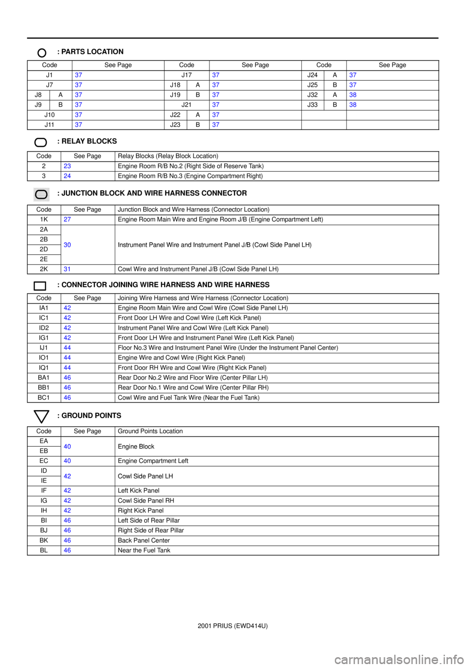
: PARTS LOCATION
CodeSee PageCodeSee PageCodeSee Page
J137J1737J24A37
J737J18A37J25B37
J8A37J19B37J32A38
J9B37J2137J33B38
J1037J22A37
J1137J23B37
: RELAY BLOCKS
CodeSee PageRelay Blocks (Relay Block Location)
223Engine Room R/B No.2 (Right Side of Reserve Tank)
324Engine Room R/B No.3 (Engine Compartment Right)
������ ���: JUNCTION BLOCK AND WIRE HARNESS CONNECTOR
CodeSee PageJunction Block and Wire Harness (Connector Location)
1K27Engine Room Main Wire and Engine Room J/B (Engine Compartment Left)
2A
2B30Instrument Panel Wire and Instrument Panel J/B (Cowl Side Panel LH)2D30Instrument Panel Wire and Instrument Panel J/B (Cowl Side Panel LH)
2E
2K31Cowl Wire and Instrument Panel J/B (Cowl Side Panel LH)
: CONNECTOR JOINING WIRE HARNESS AND WIRE HARNESS
CodeSee PageJoining Wire Harness and Wire Harness (Connector Location)
IA142Engine Room Main Wire and Cowl Wire (Cowl Side Panel LH)
IC142Front Door LH Wire and Cowl Wire (Left Kick Panel)
ID242Instrument Panel Wire and Cowl Wire (Left Kick Panel)
IG142Front Door LH Wire and Instrument Panel Wire (Left Kick Panel)
IJ144Floor No.3 Wire and Instrument Panel Wire (Under the Instrument Panel Center)
IO144Engine Wire and Cowl Wire (Right Kick Panel)
IQ144Front Door RH Wire and Cowl Wire (Right Kick Panel)
BA146Rear Door No.2 Wire and Floor Wire (Center Pillar LH)
BB146Rear Door No.1 Wire and Cowl Wire (Center Pillar RH)
BC146Cowl Wire and Fuel Tank Wire (Near the Fuel Tank)
: GROUND POINTS
CodeSee PageGround Points Location
EA40Engine BlockEB40Engine Block
EC40Engine Compartment Left
ID42Cowl Side Panel LHIE42Cowl Side Panel LH
IF42Left Kick Panel
IG42Cowl Side Panel RH
IH42Right Kick Panel
BI46Left Side of Rear Pillar
BJ46Right Side of Rear Pillar
BK46Back Panel Center
BL46Near the Fuel Tank