2001 TOYOTA PRIUS instrument panel
[x] Cancel search: instrument panelPage 114 of 1943
2001 PRIUS (EWD414U)
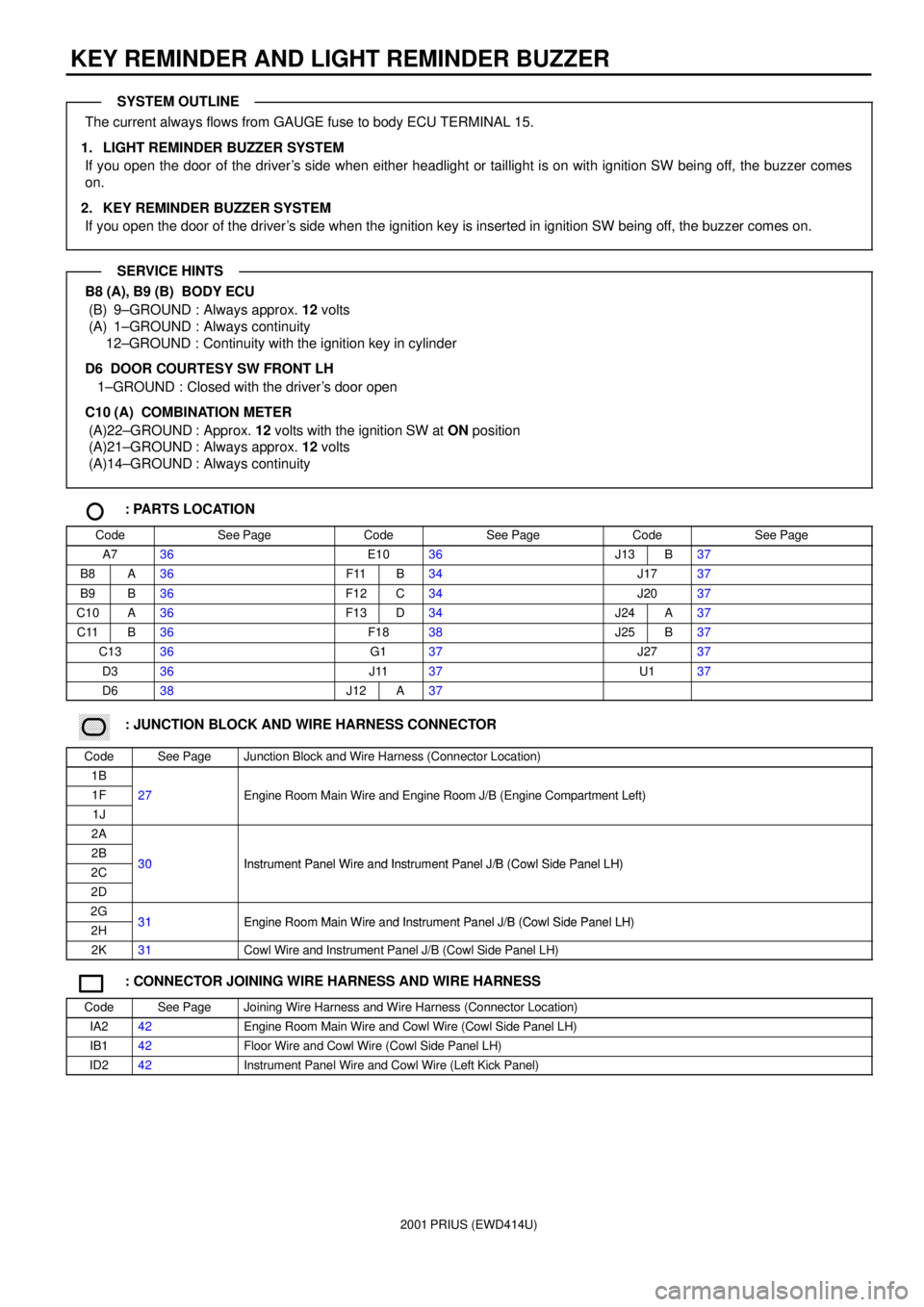
KEY REMINDER AND LIGHT REMINDER BUZZER
The current always flows from GAUGE fuse to body ECU TERMINAL 15.
1. LIGHT REMINDER BUZZER SYSTEM
If you open the door of the driver's side when either headlight or taillight is on with ignition SW being off, the buzzer comes
on.
2. KEY REMINDER BUZZER SYSTEM
If you open the door of the driver's side when the ignition key is inserted in ignition SW being off, the buzzer comes on.
B8 (A), B9 (B) BODY ECU
(B) 9±GROUND : Always approx. 12 volts
(A) 1±GROUND : Always continuity
12±GROUND : Continuity with the ignition key in cylinder
D6 DOOR COURTESY SW FRONT LH
1±GROUND : Closed with the driver's door open
C10 (A) COMBINATION METER
(A)22±GROUND : Approx. 12 volts with the ignition SW at ON position
(A)21±GROUND : Always approx. 12 volts
(A)14±GROUND : Always continuity
: PARTS LOCATION
CodeSee PageCodeSee PageCodeSee Page
A736E1036J13B37
B8A36F11B34J1737
B9B36F12C34J2037
C10A36F13D34J24A37
C11B36F1838J25B37
C1336G137J2737
D336J1137U137
D638J12A37
������ ���: JUNCTION BLOCK AND WIRE HARNESS CONNECTOR
CodeSee PageJunction Block and Wire Harness (Connector Location)
1B
1F27Engine Room Main Wire and Engine Room J/B (Engine Compartment Left)
1J
gg(g)
2A
2B30Instrument Panel Wire and Instrument Panel J/B (Cowl Side Panel LH)2C30Instrument Panel Wire and Instrument Panel J/B (Cowl Side Panel LH)
2D
2G31Engine Room Main Wire and Instrument Panel J/B (Cowl Side Panel LH)2H31Engine Room Main Wire and Instrument Panel J/B (Cowl Side Panel LH)
2K31Cowl Wire and Instrument Panel J/B (Cowl Side Panel LH)
: CONNECTOR JOINING WIRE HARNESS AND WIRE HARNESS
CodeSee PageJoining Wire Harness and Wire Harness (Connector Location)
IA242Engine Room Main Wire and Cowl Wire (Cowl Side Panel LH)
IB142Floor Wire and Cowl Wire (Cowl Side Panel LH)
ID242Instrument Panel Wire and Cowl Wire (Left Kick Panel)
SYSTEM OUTLINE
SERVICE HINTS
Page 117 of 1943
2001 PRIUS (EWD414U)
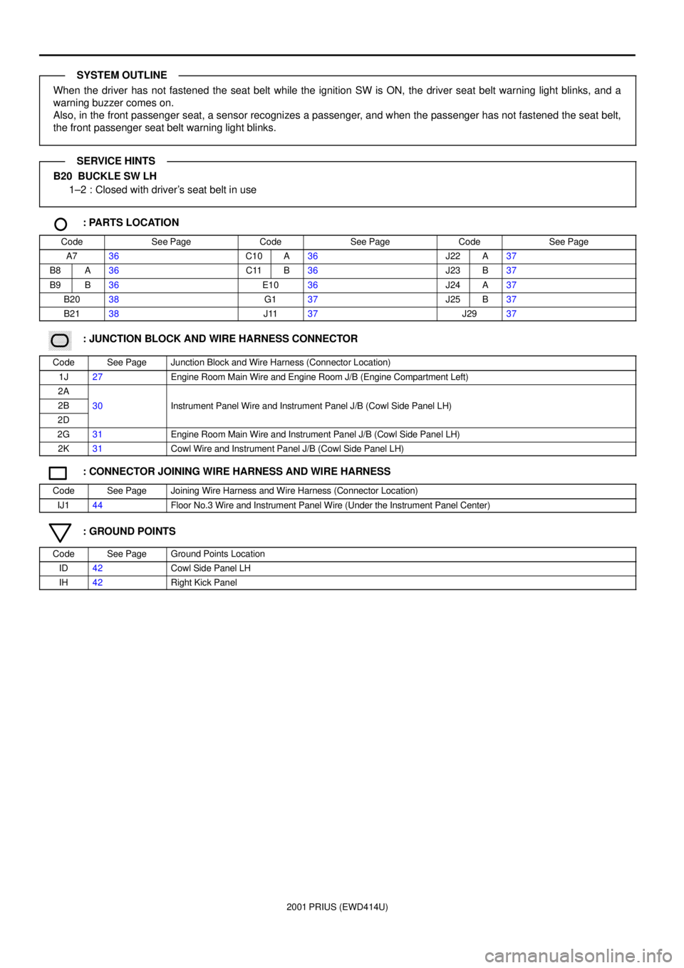
When the driver has not fastened the seat belt while the ignition SW is ON, the driver seat belt warning light blinks, and a
warning buzzer comes on.
Also, in the front passenger seat, a sensor recognizes a passenger, and when the passenger has not fastened the seat belt,
the front passenger seat belt warning light blinks.
B20 BUCKLE SW LH
1±2 : Closed with driver's seat belt in use
: PARTS LOCATION
CodeSee PageCodeSee PageCodeSee Page
A736C10A36J22A37
B8A36C11B36J23B37
B9B36E1036J24A37
B2038G137J25B37
B2138J1137J2937
������ ���: JUNCTION BLOCK AND WIRE HARNESS CONNECTOR
CodeSee PageJunction Block and Wire Harness (Connector Location)
1J27Engine Room Main Wire and Engine Room J/B (Engine Compartment Left)
2A
2B30Instrument Panel Wire and Instrument Panel J/B (Cowl Side Panel LH)
2D
()
2G31Engine Room Main Wire and Instrument Panel J/B (Cowl Side Panel LH)
2K31Cowl Wire and Instrument Panel J/B (Cowl Side Panel LH)
: CONNECTOR JOINING WIRE HARNESS AND WIRE HARNESS
CodeSee PageJoining Wire Harness and Wire Harness (Connector Location)
IJ144Floor No.3 Wire and Instrument Panel Wire (Under the Instrument Panel Center)
: GROUND POINTS
CodeSee PageGround Points Location
ID42Cowl Side Panel LH
IH42Right Kick Panel
SYSTEM OUTLINE
SERVICE HINTS
Page 119 of 1943
2001 PRIUS (EWD414U)
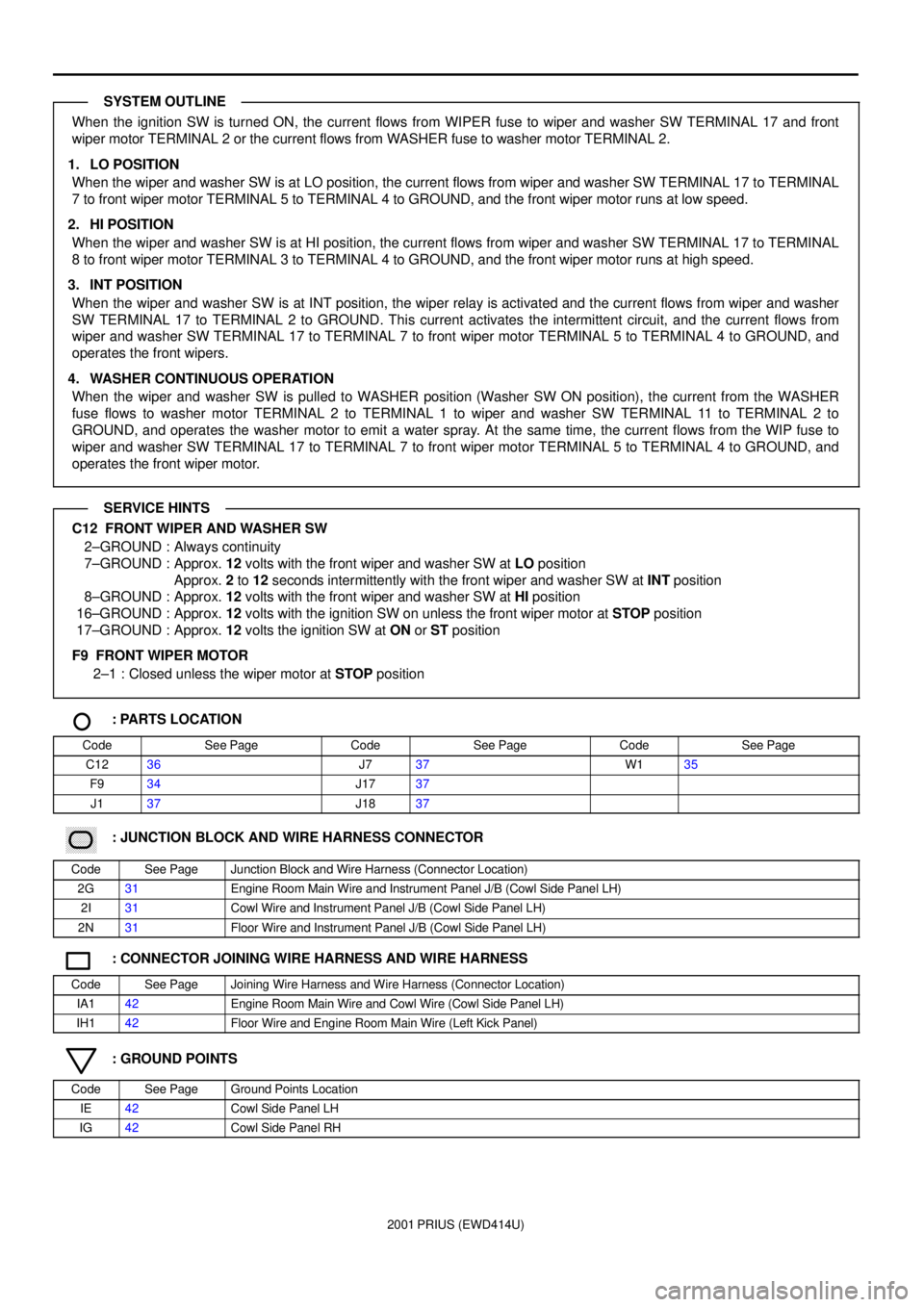
When the ignition SW is turned ON, the current flows from WIPER fuse to wiper and washer SW TERMINAL 17 and front
wiper motor TERMINAL 2 or the current flows from WASHER fuse to washer motor TERMINAL 2.
1. LO POSITION
When the wiper and washer SW is at LO position, the current flows from wiper and washer SW TERMINAL 17 to TERMINAL
7 to front wiper motor TERMINAL 5 to TERMINAL 4 to GROUND, and the front wiper motor runs at low speed.
2. HI POSITION
When the wiper and washer SW is at HI position, the current flows from wiper and washer SW TERMINAL 17 to TERMINAL
8 to front wiper motor TERMINAL 3 to TERMINAL 4 to GROUND, and the front wiper motor runs at high speed.
3. INT POSITION
When the wiper and washer SW is at INT position, the wiper relay is activated and the current flows from wiper and washer
SW TERMINAL 17 to TERMINAL 2 to GROUND. This current activates the intermittent circuit, and the current flows from
wiper and washer SW TERMINAL 17 to TERMINAL 7 to front wiper motor TERMINAL 5 to TERMINAL 4 to GROUND, and
operates the front wipers.
4. WASHER CONTINUOUS OPERATION
When the wiper and washer SW is pulled to WASHER position (Washer SW ON position), the current from the WASHER
fuse flows to washer motor TERMINAL 2 to TERMINAL 1 to wiper and washer SW TERMINAL 11 to TERMINAL 2 to
GROUND, and operates the washer motor to emit a water spray. At the same time, the current flows from the WIP fuse to
wiper and washer SW TERMINAL 17 to TERMINAL 7 to front wiper motor TERMINAL 5 to TERMINAL 4 to GROUND, and
operates the front wiper motor.
C12 FRONT WIPER AND WASHER SW
2±GROUND : Always continuity
7±GROUND : Approx. 12 volts with the front wiper and washer SW at LO position
Approx. 2 to 12 seconds intermittently with the front wiper and washer SW at INT position
8±GROUND : Approx. 12 volts with the front wiper and washer SW at HI position
16±GROUND : Approx. 12 volts with the ignition SW on unless the front wiper motor at STOP position
17±GROUND : Approx. 12 volts the ignition SW at ON or ST position
F9 FRONT WIPER MOTOR
2±1 : Closed unless the wiper motor at STOP position
: PARTS LOCATION
CodeSee PageCodeSee PageCodeSee Page
C1236J737W135
F934J1737
J137J1837
������ ���: JUNCTION BLOCK AND WIRE HARNESS CONNECTOR
CodeSee PageJunction Block and Wire Harness (Connector Location)
2G31Engine Room Main Wire and Instrument Panel J/B (Cowl Side Panel LH)
2I31Cowl Wire and Instrument Panel J/B (Cowl Side Panel LH)
2N31Floor Wire and Instrument Panel J/B (Cowl Side Panel LH)
: CONNECTOR JOINING WIRE HARNESS AND WIRE HARNESS
CodeSee PageJoining Wire Harness and Wire Harness (Connector Location)
IA142Engine Room Main Wire and Cowl Wire (Cowl Side Panel LH)
IH142Floor Wire and Engine Room Main Wire (Left Kick Panel)
: GROUND POINTS
CodeSee PageGround Points Location
IE42Cowl Side Panel LH
IG42Cowl Side Panel RH
SYSTEM OUTLINE
SERVICE HINTS
Page 121 of 1943
2001 PRIUS (EWD414U)
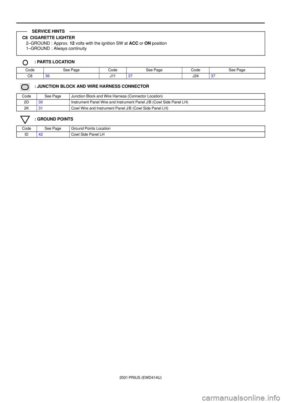
C8 CIGARETTE LIGHTER
2±GROUND : Approx. 12 volts with the ignition SW at ACC or ON position
1±GROUND : Always continuity
: PARTS LOCATION
CodeSee PageCodeSee PageCodeSee Page
C836J1137J2437
������ ���: JUNCTION BLOCK AND WIRE HARNESS CONNECTOR
CodeSee PageJunction Block and Wire Harness (Connector Location)
2D30Instrument Panel Wire and Instrument Panel J/B (Cowl Side Panel LH)
2K31Cowl Wire and Instrument Panel J/B (Cowl Side Panel LH)
: GROUND POINTS
CodeSee PageGround Points Location
ID42Cowl Side Panel LH
SERVICE HINTS
Page 126 of 1943
2001 PRIUS (EWD414U)
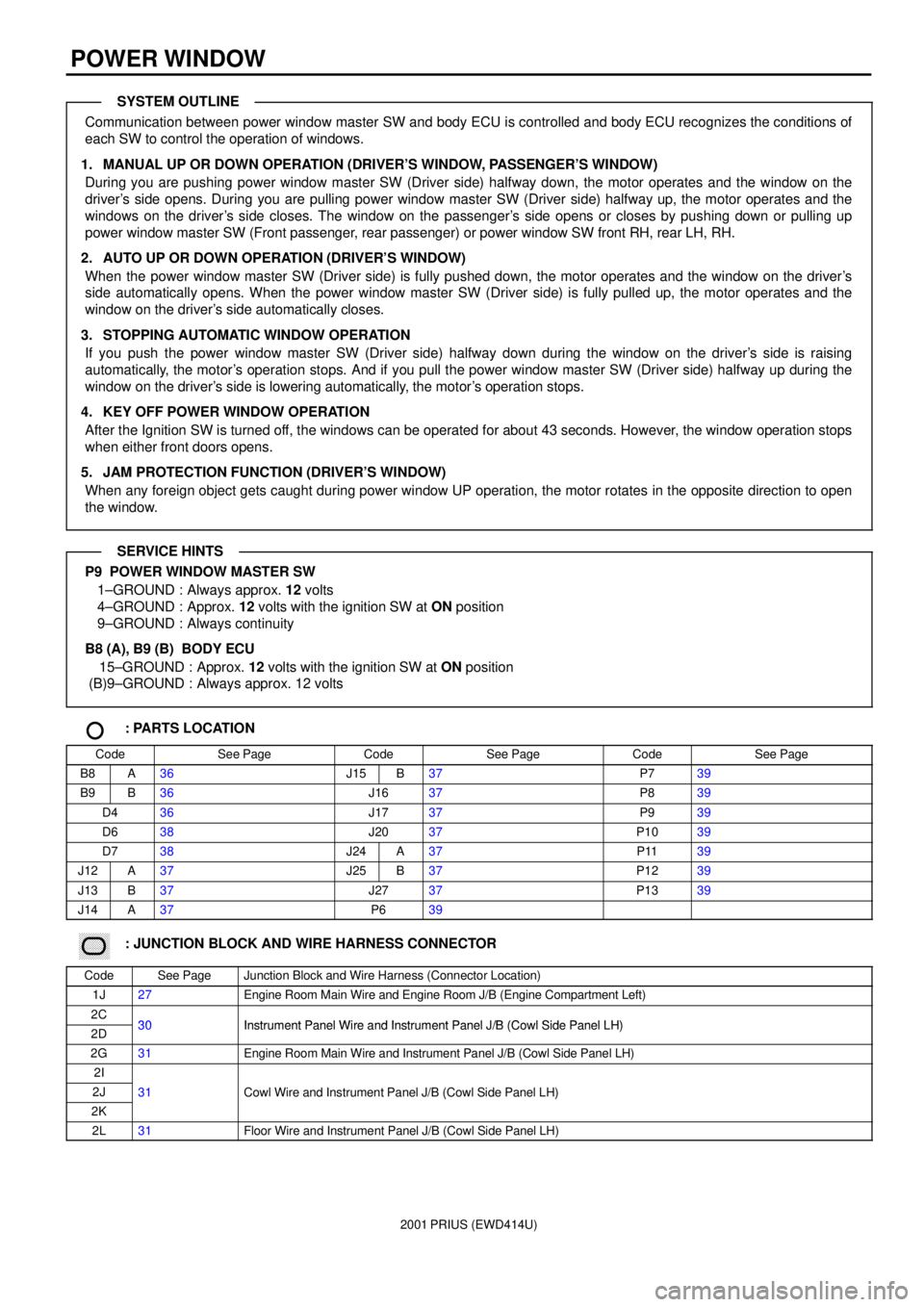
POWER WINDOW
Communication between power window master SW and body ECU is controlled and body ECU recognizes the conditions of
each SW to control the operation of windows.
1. MANUAL UP OR DOWN OPERATION (DRIVER'S WINDOW, PASSENGER'S WINDOW)
During you are pushing power window master SW (Driver side) halfway down, the motor operates and the window on the
driver's side opens. During you are pulling power window master SW (Driver side) halfway up, the motor operates and the
windows on the driver's side closes. The window on the passenger's side opens or closes by pushing down or pulling up
power window master SW (Front passenger, rear passenger) or power window SW front RH, rear LH, RH.
2. AUTO UP OR DOWN OPERATION (DRIVER'S WINDOW)
When the power window master SW (Driver side) is fully pushed down, the motor operates and the window on the driver's
side automatically opens. When the power window master SW (Driver side) is fully pulled up, the motor operates and the
window on the driver's side automatically closes.
3. STOPPING AUTOMATIC WINDOW OPERATION
If you push the power window master SW (Driver side) halfway down during the window on the driver's side is raising
automatically, the motor's operation stops. And if you pull the power window master SW (Driver side) halfway up during the
window on the driver's side is lowering automatically, the motor's operation stops.
4. KEY OFF POWER WINDOW OPERATION
After the Ignition SW is turned off, the windows can be operated for about 43 seconds. However, the window operation stops
when either front doors opens.
5. JAM PROTECTION FUNCTION (DRIVER'S WINDOW)
When any foreign object gets caught during power window UP operation, the motor rotates in the opposite direction to open
the window.
P9 POWER WINDOW MASTER SW
1±GROUND : Always approx. 12 volts
4±GROUND : Approx. 12 volts with the ignition SW at ON position
9±GROUND : Always continuity
B8 (A), B9 (B) BODY ECU
15±GROUND : Approx. 12 volts with the ignition SW at ON position
(B)9±GROUND : Always approx. 12 volts
: PARTS LOCATION
CodeSee PageCodeSee PageCodeSee Page
B8A36J15B37P739
B9B36J1637P839
D436J1737P939
D638J2037P1039
D738J24A37P1139
J12A37J25B37P1239
J13B37J2737P1339
J14A37P639
������ ���: JUNCTION BLOCK AND WIRE HARNESS CONNECTOR
CodeSee PageJunction Block and Wire Harness (Connector Location)
1J27Engine Room Main Wire and Engine Room J/B (Engine Compartment Left)
2C30Instrument Panel Wire and Instrument Panel J/B (Cowl Side Panel LH)2D30Instrument Panel Wire and Instrument Panel J/B (Cowl Side Panel LH)
2G31Engine Room Main Wire and Instrument Panel J/B (Cowl Side Panel LH)
2I
2J31Cowl Wire and Instrument Panel J/B (Cowl Side Panel LH)
2K
()
2L31Floor Wire and Instrument Panel J/B (Cowl Side Panel LH)
SYSTEM OUTLINE
SERVICE HINTS
Page 127 of 1943
2001 PRIUS (EWD414U)
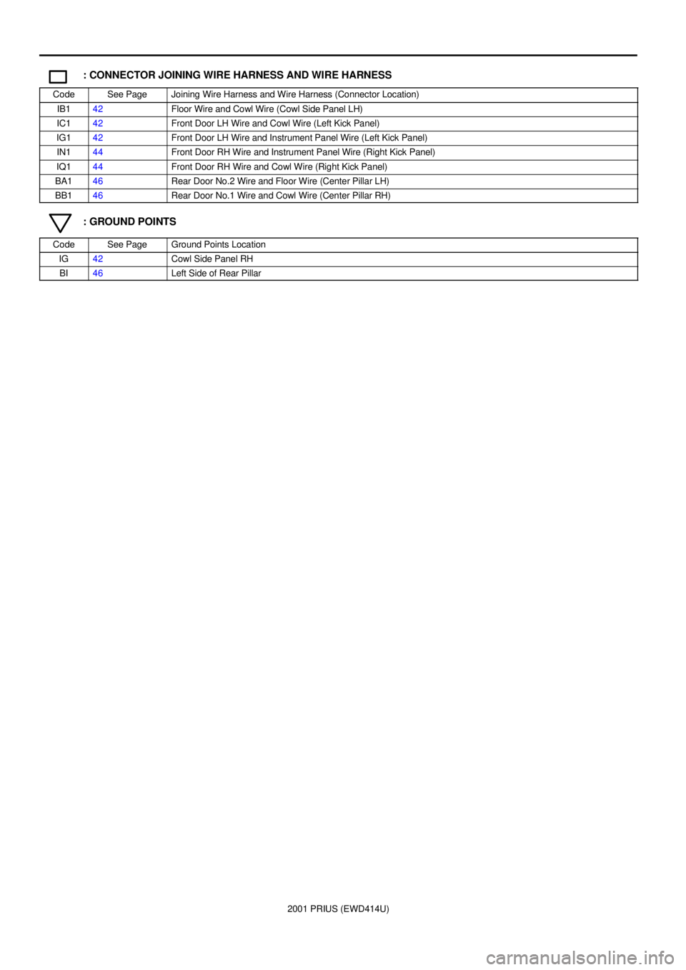
: CONNECTOR JOINING WIRE HARNESS AND WIRE HARNESS
CodeSee PageJoining Wire Harness and Wire Harness (Connector Location)
IB142Floor Wire and Cowl Wire (Cowl Side Panel LH)
IC142Front Door LH Wire and Cowl Wire (Left Kick Panel)
IG142Front Door LH Wire and Instrument Panel Wire (Left Kick Panel)
IN144Front Door RH Wire and Instrument Panel Wire (Right Kick Panel)
IQ144Front Door RH Wire and Cowl Wire (Right Kick Panel)
BA146Rear Door No.2 Wire and Floor Wire (Center Pillar LH)
BB146Rear Door No.1 Wire and Cowl Wire (Center Pillar RH)
: GROUND POINTS
CodeSee PageGround Points Location
IG42Cowl Side Panel RH
BI46Left Side of Rear Pillar
Page 129 of 1943
2001 PRIUS (EWD414U)
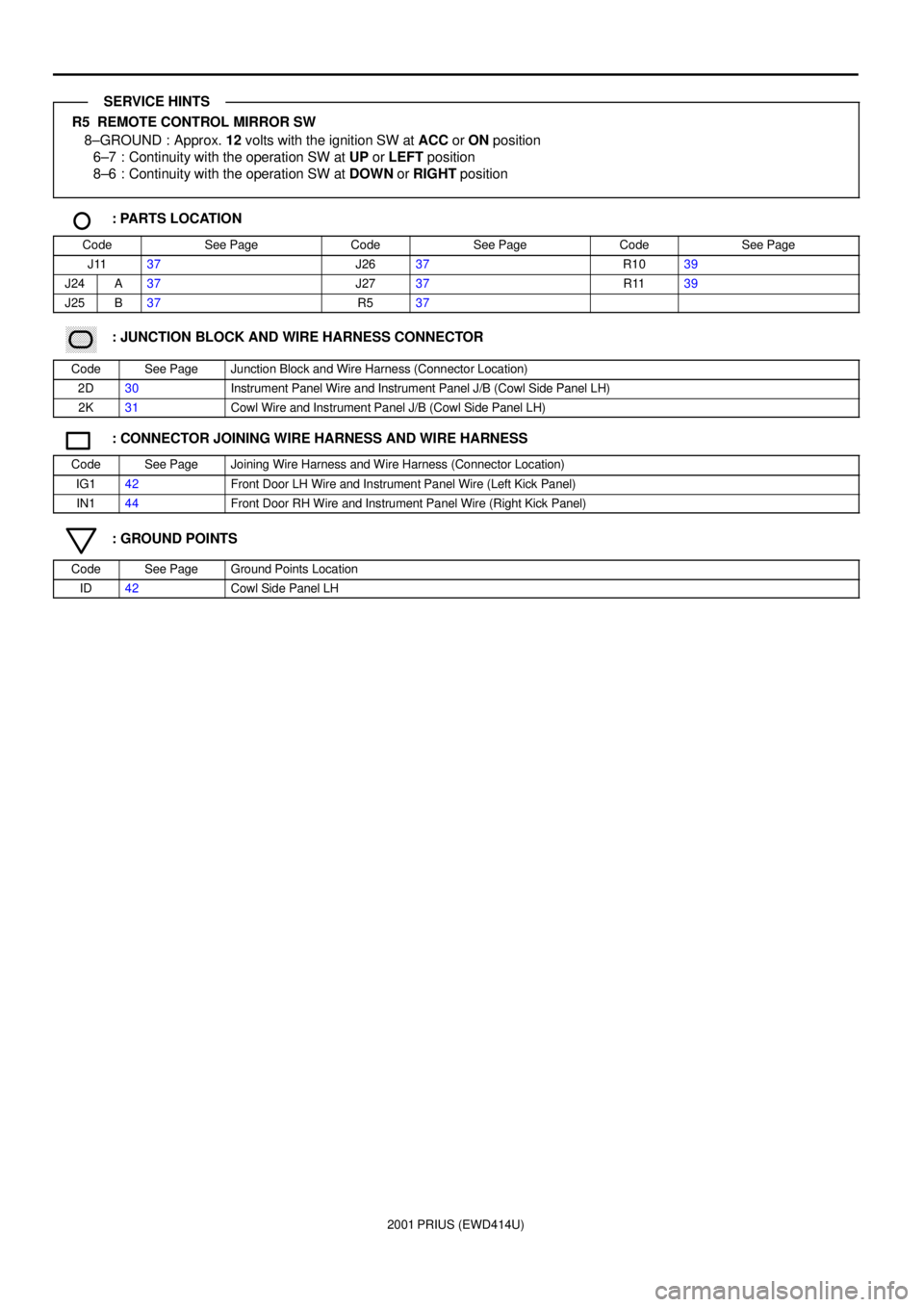
R5 REMOTE CONTROL MIRROR SW
8±GROUND : Approx. 12 volts with the ignition SW at ACC or ON position
6±7 : Continuity with the operation SW at UP or LEFT position
8±6 : Continuity with the operation SW at DOWN or RIGHT position
: PARTS LOCATION
CodeSee PageCodeSee PageCodeSee Page
J1137J2637R1039
J24A37J2737R1139
J25B37R537
������ ���: JUNCTION BLOCK AND WIRE HARNESS CONNECTOR
CodeSee PageJunction Block and Wire Harness (Connector Location)
2D30Instrument Panel Wire and Instrument Panel J/B (Cowl Side Panel LH)
2K31Cowl Wire and Instrument Panel J/B (Cowl Side Panel LH)
: CONNECTOR JOINING WIRE HARNESS AND WIRE HARNESS
CodeSee PageJoining Wire Harness and Wire Harness (Connector Location)
IG142Front Door LH Wire and Instrument Panel Wire (Left Kick Panel)
IN144Front Door RH Wire and Instrument Panel Wire (Right Kick Panel)
: GROUND POINTS
CodeSee PageGround Points Location
ID42Cowl Side Panel LH
SERVICE HINTS
Page 131 of 1943
2001 PRIUS (EWD414U)
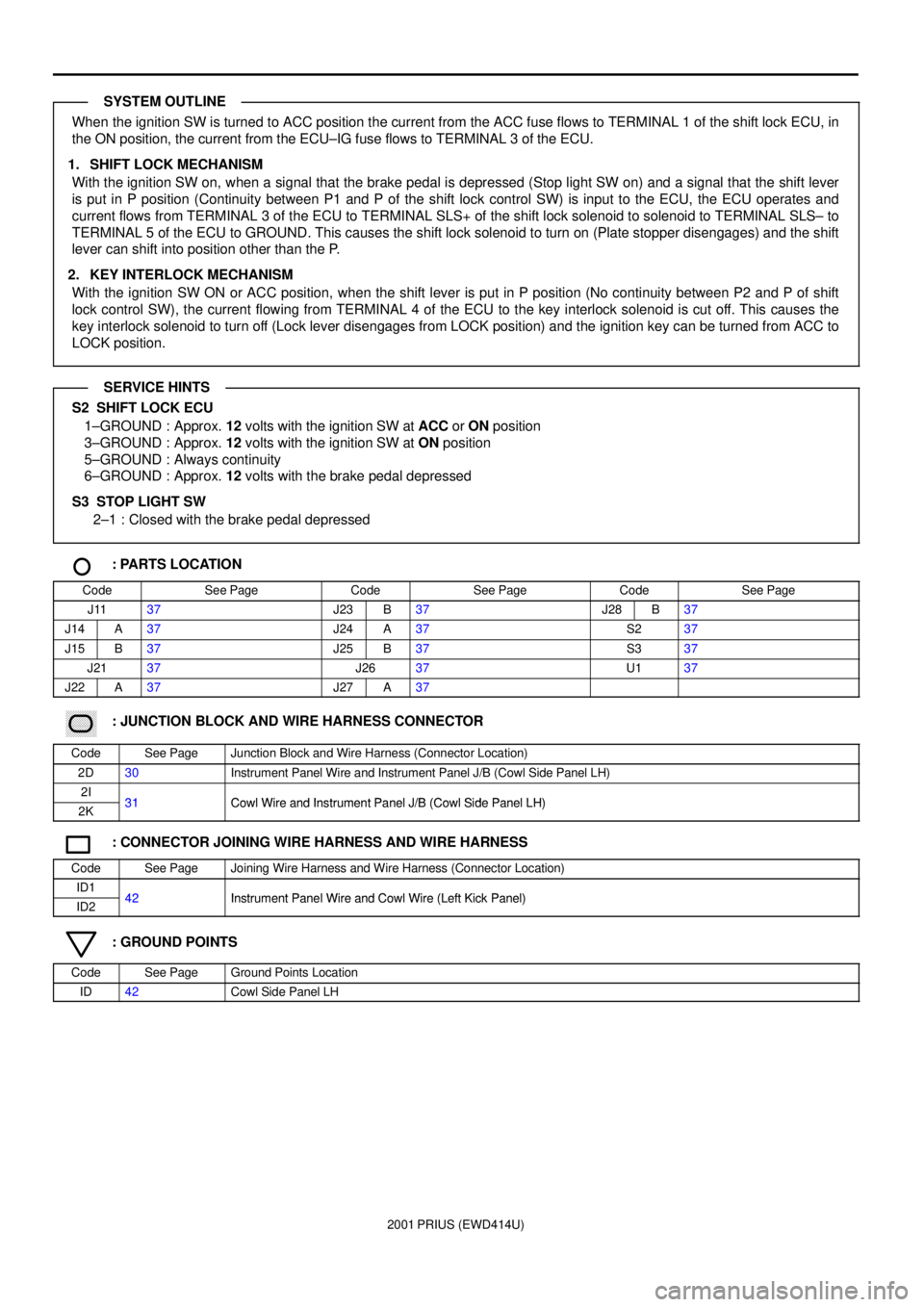
When the ignition SW is turned to ACC position the current from the ACC fuse flows to TERMINAL 1 of the shift lock ECU, in
the ON position, the current from the ECU±IG fuse flows to TERMINAL 3 of the ECU.
1. SHIFT LOCK MECHANISM
With the ignition SW on, when a signal that the brake pedal is depressed (Stop light SW on) and a signal that the shift lever
is put in P position (Continuity between P1 and P of the shift lock control SW) is input to the ECU, the ECU operates and
current flows from TERMINAL 3 of the ECU to TERMINAL SLS+ of the shift lock solenoid to solenoid to TERMINAL SLS± to
TERMINAL 5 of the ECU to GROUND. This causes the shift lock solenoid to turn on (Plate stopper disengages) and the shift
lever can shift into position other than the P.
2. KEY INTERLOCK MECHANISM
With the ignition SW ON or ACC position, when the shift lever is put in P position (No continuity between P2 and P of shift
lock control SW), the current flowing from TERMINAL 4 of the ECU to the key interlock solenoid is cut off. This causes the
key interlock solenoid to turn off (Lock lever disengages from LOCK position) and the ignition key can be turned from ACC to
LOCK position.
S2 SHIFT LOCK ECU
1±GROUND : Approx. 12 volts with the ignition SW at ACC or ON position
3±GROUND : Approx. 12 volts with the ignition SW at ON position
5±GROUND : Always continuity
6±GROUND : Approx. 12 volts with the brake pedal depressed
S3 STOP LIGHT SW
2±1 : Closed with the brake pedal depressed
: PARTS LOCATION
CodeSee PageCodeSee PageCodeSee Page
J1137J23B37J28B37
J14A37J24A37S237
J15B37J25B37S337
J2137J2637U137
J22A37J27A37
������ ���: JUNCTION BLOCK AND WIRE HARNESS CONNECTOR
CodeSee PageJunction Block and Wire Harness (Connector Location)
2D30Instrument Panel Wire and Instrument Panel J/B (Cowl Side Panel LH)
2I31Cowl Wire and Instrument Panel J/B (Cowl Side Panel LH)2K31Cowl Wire and Instrument Panel J/B (Cowl Side Panel LH)
: CONNECTOR JOINING WIRE HARNESS AND WIRE HARNESS
CodeSee PageJoining Wire Harness and Wire Harness (Connector Location)
ID142Instrument Panel Wire and Cowl Wire (Left Kick Panel)ID242Instrument Panel Wire and Cowl Wire (Left Kick Panel)
: GROUND POINTS
CodeSee PageGround Points Location
ID42Cowl Side Panel LH
SYSTEM OUTLINE
SERVICE HINTS