Page 1567 of 1943
B11461
Throttle BodyTrottle Position Sensor
N´m (kgf´cm, ft´lbf) : Specified torque
1.7 (17.5, 15 in.´lbf)
± SFITHROTTLE BODY
SF±27
2001 PRIUS (RM778U)
Page 1568 of 1943

(2)
B11467Turn
± SFITHROTTLE BODY
SF±29
2001 PRIUS (RM778U)
REPLACEMENT
NOTICE:
�To prevent deterioration, do not shock the throttle
position sensor.
�Mixing of the")
SF1KT±01
B11465
B1146615° (3)
(2)
B11467Turn
± SFITHROTTLE BODY
SF±29
2001 PRIUS (RM778U)
REPLACEMENT
NOTICE:
�To prevent deterioration, do not shock the throttle
position sensor.
�Mixing of the foreign objects may cause the gear lock-
ing, so thoroughly check that there is no stuck of any
foreign objects and clean up if any.
REPLACE THROTTLE POSITION SENSOR
(a) Remove the 2 set screws and throttle position sensor.
(b) Reinstall the throttle position sensor.
(1) Check that the throttle valve is under the condition
of the opener opening angle (about 3.5°).
(2) Install the sensor to the place where is at 15° ro-
tated to the right from the specified installation posi-
tion.
(3) Gradually turn sensor counterclockwise until it
touches the throttle valve shaft and temporarily
torque the 2 set screws.
(c) Adjust the throttle position sensor.
(1) Connect the throttle position sensor connector.
NOTICE:
At this time, do not connect the throttle control motor con-
nector.
(2) Connect the TOYOTA hand±held tester to the
DLC3.
(3) Turn the ignition switch ON.
NOTICE:
After turning the ignition switch ON, do not depress the ac-
celerator pedal.
(4) While reading the value of the throttle valve opening
percentage (THROTTLE POS) of the CURRENT
DATA, turn the throttle position sensor slowly to left
and set the sensor at the center value of the stan-
dard value, and then torque the screws.
Torque: 1.7 N´m (17.5 kgf´cm, 15 in.´lbf)
Standard throttle valve opening percentage:
14.8 ± 0.8 %
Page 1569 of 1943
SF±30
± SFITHROTTLE BODY
2001 PRIUS (RM778U)
NOTICE:
At the time of tightening the screw, as the sensor itself
tends to turn causing to slanting, check that it is within the
standard value after having finished the torque.
(5) Fully close the throttle valve with a screwdriver and
check that the value of the throttle valve opening
percentage (THROTTLE POS) of the CURRENT
DATA stays with the standard value.
Standard throttle valve opening percentage:
10 ± 14 %
If the throttle valve opening percentage is not as specified, re-
peat steps (4) through (5).
(6) Paint the sensor set screws.
(7) Turn the ignition switch OFF.
(8) Disconnect the TOYOTA hand±held tester or from
the DLC3.
(9) Disconnect the throttle position sensor connector.
Page 1588 of 1943

SPARK TEST
Replace the crankshaft position sensor.
CHECK RESISTANCE OF CAMSHAFT POSITION
1. Turn ignition switch to ON.
2. Check that ther")
CHECK POWER SUPPLY TO IGNITION COIL (WITH
SENSOR (See step 3)
SPARK TEST
Replace the crankshaft position sensor.
CHECK RESISTANCE OF CAMSHAFT POSITION
1. Turn ignition switch to ON.
2. Check that there is battery voltage at ignition coil positive (+)
terminal.
CHECK CONNECTION OF IGNITION COIL
CONNECTOR
Resistance:Cold Hot
CHECK RESISTANCE OF CRANKSHAFT POSITION
Resistance:Cold Hot 1,630 ± 2,740 W2,065 ± 3.225 W
CHECK IGT SIGNAL FROM ECM
(See page
DI±115)
TRY ANOTHER IGNITION COIL (WITH IGNITER)
Replace the camshaft position sensor. Connect securely.
Check wiring between ignition switch
to ignition coil (with igniter).
Check wiring between ECM and ignition
coil (with igniter), and then try another ECM.
NO
OK
OK
OK
OKBAD
BAD
BAD
BAD
BAD
SENSOR (See step 4) IGNITER) CHANGE IT TO NORMAL IGNITION COIL (WITH
IGNITER) AND PERFORM SPARK TEST AGAIN
OKReplace the ignition coil (with igniter).
NO
OK
985 ± 1,600 W1,265 ± 1,890 W
B11755
16 mm (0.63 in.)
Plug Wrench IG±2
± IGNITIONIGNITION SYSTEM
1319 Author�: Date�:
2001 PRIUS (RM778U)
If the spark does not occur, do the test as follows:
(7) Using a 16 mm (0.63 in.) plug wrench, install the
spark plugs.
Torque: 18 N´m (184 kgf´cm, 13 ft´lbf)
(8) Install the ignition coils (with igniter) (See page
IG±7).
2. INSPECT SPARK PLUGS
(a) Remove the ignition coils (with igniter) (See page
IG±6).
(b) Using a 16 mm (0.63 in.) plug wrench, remove the spark
plugs.
Page 1589 of 1943

(c) Clean the spark plugs.
If the electrode has traces of wet carbon, allow it to dry and")
IG0152
IG0148
B02101
B11756
B11757
± IGNITIONIGNITION SYSTEM
IG±3
1320 Author�: Date�:
2001 PRIUS (RM778U)
(c) Clean the spark plugs.
If the electrode has traces of wet carbon, allow it to dry and then
clean with a spark plug cleaner.
Air pressure: Below 588 kPa (6 kgf/cm
2, 85 psi)
Duration: 20 seconds or less
HINT:
If there are traces of oil, remove it with gasoline before using the
spark plug cleaner.
(d) Check the spark plug for thread damage and insulator
damage.
If abnormal, replace the spark plug.
Recommended spark plug:
DENSO madeSK16R11
NGK madeIFR5A11
(e) Check the electrode gap.
Electrode gap: 1.0 ± 1.1 mm (0.039 ± 0.043 in.)
Maximum electrode gap: 1.2 mm (0.047 in.)
If the electrode gap is greater than maximum, replace the spark
plug.
(f) Using a 16 mm (0.63 in.) plug wrench, install the spark
plugs.
Torque: 18 N´m (184 kgf´cm, 13 ft´lbf)
(g) Install the ignition coils (with igniter) (See page IG±7).
3. INSPECT CAMSHAFT POSITION SENSOR
(a) Disconnect the camshaft position sensor connector.
(b) Using an ohmmeter, measure the resistance between ter-
minals.
Resistance:
Cold1,630 ± 2,740 W
Hot2,065 ± 3,225 W
If the resistance is not as specified, replace the camshaft posi-
tion sensor.
(c) Connect the camshaft position sensor connector.
Page 1590 of 1943
B11758
B11759
IG±4
± IGNITIONIGNITION SYSTEM
1321 Author�: Date�:
2001 PRIUS (RM778U)
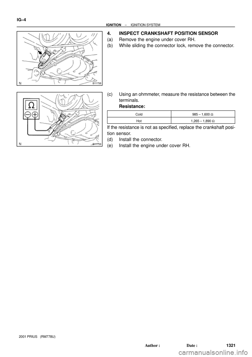
4. INSPECT CRANKSHAFT POSITION SENSOR
(a) Remove the engine under cover RH.
(b) While sliding the connector lock, remove the connector.
(c) Using an ohmmeter, measure the resistance between the
terminals.
Resistance:
Cold985 ± 1,600 W
Hot1,265 ± 1,890 W
If the resistance is not as specified, replace the crankshaft posi-
tion sensor.
(d) Install the connector.
(e) Install the engine under cover RH.
Page 1603 of 1943
HV009±01
B11975
Wiper Arm and Blade Assembly
Wiper Motor
w/ Wiper Link
Cowl Top Ventilator
Louver
N´m (kgf´cm, ft´lbf) : Specified torque
8.0 (82, 71 in.´lbf)
Hood to Cowl Top SealCowl Top Panel
Power Cable Connector
Converter
Connector
Inverter
Connector Inverter Terminal
Cover
� Gasket
Converter & Inverter
Assembly
MG1 Power CableConnector CoverCircuit Breaker Sensor
Water HoseWater Hose
20 (204, 15)
21 (214, 15)8.0 (82, 71 in.´lbf)
7.0 (71, 62 in.´lbf)MG2 Power Cable
8.0 (82, 71 in.´lbf)
19.5 (199, 14)
� Non±reusable part HV±16
± HYBRID VEHICLE CONTROLCONVERTER AND INVERTER ASSEMBLY
2001 PRIUS (RM778U)
COMPONENTS
Page 1605 of 1943

REMOVAL
1. REMOVE SERVICE PLUG (See page HV±1)
2. DRAIN HV COOLANT (See page HT±")
HV00A±01
B11977
B11979
B11980
HV±18
± HYBRID VEHICLE CONTROLCONVERTER AND INVERTER ASSEMBLY
2001 PRIUS (RM778U)
REMOVAL
1. REMOVE SERVICE PLUG (See page HV±1)
2. DRAIN HV COOLANT (See page HT±6)
3. REMOVE COWL TOP PANEL (See page BO±31)
4. VERIFY 0 V
NOTICE:
�Before starting step (a), 5 minutes or more should be
passed after removing the service plug.
�Be careful to prevent foreign matter from entering the
inside of connector cover.
(a) Disconnect the connector of the battery power cable and
insulate it with packaging tape.
(b) Using a torx socket wrench (T30), remove the 4 screws
and inverter terminal cover.
(c) Using a torx socket wrench (T40), remove the 2 screws,
circuit breaker sensor and connector cover.
HINT:
Slide the connector cover to disconnect the circuit breaker sen-
sor connector.
(d) Using a voltmeter, measure the voltage between termi-
nals of 3 phases (U±V, V±W, U±W) and each terminal and
body ground to verify them to be approx. 0 V.
5. REMOVE CONVERTER & INVERTER ASSEMBLY
(a) Remove the 6 bolts and 3 power cables for MG2.
NOTICE:
Be careful to prevent foreign matter from entering the in-
side of connector cover.
(b) Remove the 3 bolts and power cable for MG1.
NOTICE:
�Remove the power cable for MG1 together with con-
verter & inverter assembly.
�Be careful to prevent foreign matter from entering the
inside of connector cover.
(c) Remove the bolt and ground cable.
 : Specified torque
1.7 (17.5, 15 in.´lbf)
± SFITHROTTLE BODY
SF±27
2001 PRIUS (RM778U)")

NOTICE:
At the time of tightening the screw, as the sensor itself
tends to turn causing to slanting, check that it is within the
standard value after")
 : Specified torque
8.0 (82, 71 in.´lbf)
Hood to Cowl Top SealCowl Top Pane")