Page 1725 of 1943
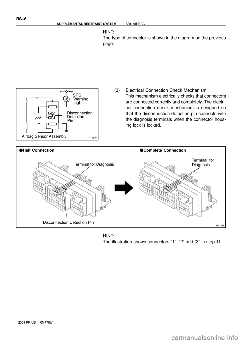
R12076Airbag Sensor AssemblyDisconnection
Detection
PinSRS
Warning
Light
H01315
Terminal for Diagnosis
Disconnection Detection Pin �Half Connection�Complete Connection
Terminal for
Diagnosis
RS±6
± SUPPLEMENTAL RESTRAINT SYSTEMSRS AIRBAG
2001 PRIUS (RM778U)
HINT:
The type of connector is shown in the diagram on the previous
page.
(3) Electrical Connection Check Mechanism
This mechanism electrically checks that connectors
are connected correctly and completely. The electri-
cal connection check mechanism is designed so
that the disconnection detection pin connects with
the diagnosis terminals when the connector hous-
ing lock is locked.
HINT:
The illustration shows connectors º1º, º2º and º3º in step 11.
Page 1726 of 1943

Z14034
Fig.1
Fig.2Power Source
Safing
Sensor
Squibs
Deceleration Sensor
H01581
Outer
H01582
Lock of connector is released
Disconnection is completed
± SUPPLEMENTAL RESTRAINT SYSTEMSRS AIRBAG
RS±7
2001 PRIUS (RM778U)
(b) When the vehicle is involved in a frontal collision in the
hatched area (Fig. 1) and the shock is larger than the pre-
determined level, the SRS is activated automatically. A
safing sensor is designed to go on at a smaller decelera-
tion rate than the airbag sensor. As illustrated in Fig. 2,
ignition is caused when current flows to the squib, which
happens when a safing sensor and the deceleration sen-
sor go on simultaneously. When a deceleration force acts
on the sensors, 2 squibs in the driver airbag and front pas-
senger airbag ignite and generate gas. The gas discharg-
ing into the driver airbag and front passenger airbag rap-
idly increases the pressure inside the bags, breaking
open the steering wheel pad and instrument panel.
Bag inflation then ends, and the bags deflate as the gas
is discharged through discharge holes at the bag's rear or
side.
11. DISCONNECTION OF CONNECTORS FOR FRONT
AIRBAG SENSOR AND SIDE AIRBAG SENSOR
(a) While holding both flank sides of the outer, slide the outer
to the direction shown by an arrow.
(b) Lock of the connectors is released, then disconnect the
connectors.
HINT:
Be sure to hold both flank sides of the outer. If holding the top
and bottom sides, it will obstruct disconnection.
Page 1727 of 1943
H01583
Outer
Outer
RS±8
± SUPPLEMENTAL RESTRAINT SYSTEMSRS AIRBAG
2001 PRIUS (RM778U)
12. CONNECTION OF CONNECTORS FOR FRONT AIR-
BAG SENSOR AND SIDE AIRBAG SENSOR
(a) Align the male connector (of the side of sensor) and fe-
male connector in the same direction as shown in the il-
lustration and fit in them without rubbing.
(b) As they are fitted in, the outer slides rearward. Press it un-
til the outer returns to its original position again.
If fitting stops half way, connectors will separate.
(c) Be sure to insert until they are locked. After fitting in, pull
them slightly to check that they are locked. (When locked,
make sure that the outer returns to its original position and
sound at the time of fitting in can be heard.)
HINT:
�Do not fit in while holding the outer.
�When fitting in, the outer slides. Do not touch it.
Page 1763 of 1943

WIPER AND WASHER SYSTEM
SymptomSuspect AreaSee page
Wipers and washer do not operate.
1. WIPER Fuse
2. Wiper Switch")
BE±6
± BODY ELECTRICALTROUBLESHOOTING
1673 Author�: Date�:
2001 PRIUS (RM778U)
WIPER AND WASHER SYSTEM
SymptomSuspect AreaSee page
Wipers and washer do not operate.
1. WIPER Fuse
2. Wiper Switch
3. Wiper Motor
4. Wire HarnessBE±12
BE±34
BE±34
±
Wipers do not operate in LO, HI or MIST.
1. Wiper Switch
2. Wiper Motor
3. Wire HarnessBE±34
BE±34
±
Wipers do not operate in INT.
1. Wiper Switch
2. Wiper Motor
3. Wire HarnessBE±34
BE±34
±
Washer motor does not operate.
1. WASHER Fuse
2. Washer Switch
3. Washer Motor
4. Wire HarnessBE±12
BE±34
BE±34
±
Wipers do not operate when washer switch ON.
1. WASHER Fuse
2. Washer Switch
3. Wiper Motor
4. Wire HarnessBE±12
BE±34
BE±34
±
Washer fluid does not operate.Washer Hose and Nozzle±
� When wiper switch is in HI position, the wiper blade is in contact
with the body.
� When the wiper switch is OFF, the wiper blade does not retract
or the retract position is wrong.
1. Wiper Motor *1
2. Wire harness *1BE±34
±
*1: Inspect wiper arm and blade set positions.
Meter Gauges and Illumination:
COMBINATION METER
SymptomSuspect AreaSee page
Fuel Gauge and Water Temperature Gauge does not operate.
1. GAUGE Fuse
2. Meter Circuit Plate
3. Wire Harness±
BE±39
±
Speedometer does not operate.
1. Vehicle Speed Sensor
2. Meter Circuit Plate
3. Wire HarnessBE±42
BE±39
±
Tachometer does not operate.
1. Igniter
2. Engine and ECT ECU
3. Meter Circuit Plate
4. Wire Harness±
±
BE±39
±
Fuel Gauge does not operate or abnormal operation.1. Fuel Tank Assembly
2. Wire Harness±
±
All illumination lights do not light up.
1. TAIL Fuse
2. Meter Circuit Plate
3. Wire Harness±
BE±42
±
Only one illumination light does not light up.1. Bulb
2. Wire Harness±
±
Page 1764 of 1943

Warning Lights:
COMBINATION METER
SymptomSuspect AreaSee page
Warning light do not light up. (Except Discharge, Open")
± BODY ELECTRICALTROUBLESHOOTING
BE±7
1674 Author�: Date�:
2001 PRIUS (RM778U)
Warning Lights:
COMBINATION METER
SymptomSuspect AreaSee page
Warning light do not light up. (Except Discharge, Open Door and
SRS)
1. GAUGE Fuse
2. Meter Circuit Plate
3. DC/DC converter
4. Wire Harness±
BE±39
±
±
Fuel Level warning light does not light up.
1. Bulb
2. Meter Circuit Plate
3. Fuel Tank Assembly
4. Wire Harness±
BE±39
±
±
Low Oil Pressure warning light does not light up.
1. Bulb
2. Low Oil Pressure Warning Switch
3. Meter Circuit Plate
4. Wire Harness±
BE±42
BE±39
±
ABS warning light does not light up.
1. Bulb
2. ABS ECU
3. Wire Harness±
DI±351
±
Seat Belt warning light does not light up.
1. Bulb
2. Buckle Switch
3. Meter Circuit
4. Wire Harness±
BE±42
BE±42
±
Brake warning light does not light up.
1. Bulb
2. Parking Brake Switch
3. Brake Fluid Level Warning Switch
4. Meter Circuit Plate
5. Wire Harness±
BE±42
BE±42
BE±39
±
SRS Warning light does not light up.
1. Bulb
2. Airbag Sensor Assembly
3. Meter Circuit Plate
4. Wire Harness±
DI±495
BE±39
±
Open Door warning light does not light up.
1. DOME Fuse
2. Bulb
3. Door Courtesy Switch
4. Meter Circuit Plate
5. Wire Harness±
±
BE±27
BE±39
±
Indicator Lights:
COMBINATION METER
SymptomSuspect AreaSee page
High beam indicator light does not light up.
1. Bulb
2. Meter Circuit Plate
3. Wire Harness
4. Headlight System±
BE±39
±
BE±20
Turn indicator light does not light up.
1. Bulb
2. Meter Circuit Plate
3. Wire Harness
4. Turn Signal and Hazard Warning System±
BE±39
±
BE±25
Malfunction indicator light does not light up.
1. Bulb
2. ECM
3. Meter Circuit Plate
4. Wire Harness±
±
BE±39
±
Indicator lights do not light up. (Except Turn, Hi±beam and
security)1. GAUGE Fuse
2. Wire Harness±
±
Page 1765 of 1943
 Shift position indicator light does not light up.
1. ECM
2. Shift Position Sensor
3. HV ECU
4. Meter Circuit Plate
5.")
BE±8
± BODY ELECTRICALTROUBLESHOOTING
1675 Author�: Date�:
2001 PRIUS (RM778U) Shift position indicator light does not light up.
1. ECM
2. Shift Position Sensor
3. HV ECU
4. Meter Circuit Plate
5. Wire Harness±
HT±54
±
BE±39
±
CRUISE indicator light does not light up.
1. Bulb
2. HV ECU
3. Meter Circuit Plate
4. Wire Harness±
±
BE±39
±
DEFOGGER SYSTEM
This system uses the multiplex communication system, so check diagnosis system of the multiplex commu-
nication system before you proceed with troubleshooting.
SymptomSuspect AreaSee page
Rear window defogger does not operate.
1. DEF M±Fuse
2. Defogger Relay
3. Defogger Switch (in A/C Amplifier)
4. Defogger Wire
5. Wire Harness
6. Body ECU
7. Noise Filter
8. A/C ECUBE±12
BE±49
DI±864
BE±49
±
DI±678
±
DI±864
Mirror heater does not operate.
1. M±HTR Fuse (Passenger SIde J/B)
2. Mirror Heater Relay
3. Mirror Heater
4. Wire HarnessBE±12
BE±49
BE±49
±
POWER WINDOW CONTROL SYSTEM
This system uses the multiplex communication system, so check diagnosis system of the multiplex commu-
nication system before you proceed with troubleshooting.
SymptomSuspect AreaSee page
Power window dose not operate.
1. ECU B Fuse
2. GAUGE Fuse
3. Power Main Relay
4. Ignition Switch
5. Power Window Master Switch
6. Body ECU
7. Wire HarnessBE±12
BE±12
BE±56
BE±17
BE±56
DI±678
±
Only the driver's window does not operate.
1. Power Window Master Switch
2. Power Window Switch
3. Power Window Motor
4. Wire HarnessBE±56
BE±56
BE±56
±
ºWindow lock functionº does not operate.Power Window Master SwitchBE±56
Illumination does not light up.Power Window Master SwitchBE±56
Page 1782 of 1943
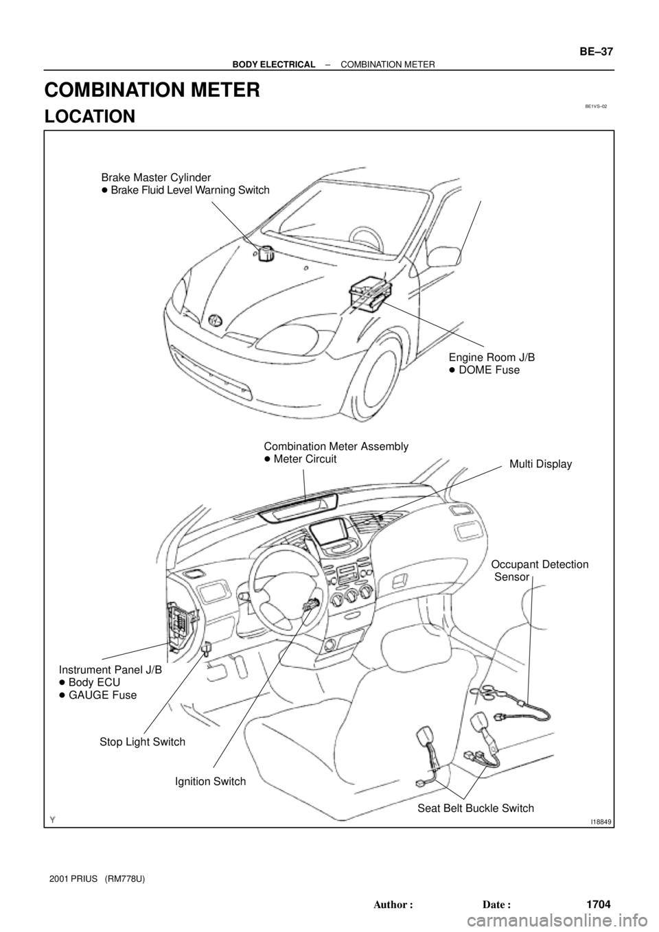
BE1VS±02
I18849
Brake Master Cylinder
� Brake Fluid Level Warning Switch
Combination Meter Assembly
� Meter Circuit
Multi Display
Ignition Switch
Instrument Panel J/B
� Body ECU
� GAUGE Fuse
Stop Light Switch
Engine Room J/B
� DOME Fuse
Seat Belt Buckle Switch
Occupant Detection
Sensor
± BODY ELECTRICALCOMBINATION METER
BE±37
1704 Author�: Date�:
2001 PRIUS (RM778U)
COMBINATION METER
LOCATION
Page 1786 of 1943
No. Wiring connector side
1
2
3
10
11
12
13
14
15
16
17
18
19
20
21
22EMPS ECU
Fuel tank temperature (+)
Hybrid vehicle control ECU (4P)
Ground
Ground
Center airbag sensor assembly
Headlight dimmer switch
Turn signal switch (Right)
Turn signal switch (Left)
Fuel tank temperature (±)
DOME Fuse
GAUGE FuseODO/TRIP switch (TC)
ODO/TRIP switch (E)
ODO/TRIP switch (ODO)
9 ABS ECU (SI)
ABS ECU (ABS)
2
3
4
5
6
7 1 Back±up light relay
Body ECU
Engine ECM
ACC Fuse
Light control rheostat (TC)
Light control rheostat (TR) A
BBody ECU
± BODY ELECTRICALCOMBINATION METER
BE±41
2001 PRIUS (RM778U)

12. CONNECTION OF CONNECTORS FOR FRONT AIR-
BAG SENSOR AND SIDE AIRBAG SENSOR
(a) Align the male connector (o")

Hybrid vehicle control ECU (4P)
Ground
Ground
Center airbag sensor assembly
Headlight dimmer sw")