Page 1540 of 1943
EC0HT±01
B11797
Charcoal Canister VSV for EVAP
Heated Oxygen Sensor
(Bank 1 Sensor 1)
Heated Oxygen Sensor
(Bank 1 Sensor 2) Fuel Tank
Air Cleaner
Throttle Valve
Pressure Sensor
for HCAC
Check
Valve VSV for HCAC
Actuator for HCAC
Refer to next page
± EMISSION CONTROLPARTS LAYOUT AND SCHEMATIC DRAWING
EC±3
2001 PRIUS (RM778U)
DRAWING
Page 1541 of 1943
B11798
Air Cleaner
Throttle Valve
VSV for
EVAP
Purge Line
VSV for Purge Flow
Switching Valve
Charcoal
Canister
EVAP Line
Fuel Tank Vapor Pressure
Sensor Trap Filter Fresh Air
Valve
Canister Closed
Valve Filler Pipe
EC±4
± EMISSION CONTROLPARTS LAYOUT AND SCHEMATIC DRAWING
2001 PRIUS (RM778U)
Page 1550 of 1943

SFI SYSTEM
PRECAUTION
1. BEFORE WORKING ON THE FUEL SYSTEM , DIS-
CONNECT THE NEGATIVE (±) TERMINAL CABLE
FROM THE BATTERY")
SF1KN±01
± SFISFI SYSTEM
SF±1
1215 Author�: Date�:
2001 PRIUS (RM778U)
SFI SYSTEM
PRECAUTION
1. BEFORE WORKING ON THE FUEL SYSTEM , DIS-
CONNECT THE NEGATIVE (±) TERMINAL CABLE
FROM THE BATTERY AND HV BATTERY SERVICE
PLUG
HINT:
Any diagnostic trouble code retained by the computer will be
erased when the negative (±) terminal cable is removed from
the battery. Therefore, if necessary, read the diagnosis before
removing the negative (±) terminal cable from the battery.
2. DO NOT SMOKE OR WORK NEAR AN OPEN FLAME
WHEN WORKING ON THE FUEL SYSTEM
3. KEEP GASOLINE AWAY FROM RUBBER OR
LEATHER PARTS
4. MAINTENANCE PRECAUTIONS
(a) In event of engine misfire, these precautions should be
taken.
(1) Check proper connection to battery terminals, etc.
(2) After repair work, check that the ignition coil termi-
nals and all other ignition system lines are recon-
nected securely.
(3) When cleaning the engine compartment, be espe-
cially careful to protect the electrical system from
water.
(b) Precautions when handling oxygen sensor.
(1) Do not allow oxygen sensor to drop or hit against an
object.
(2) Do not allow the sensor to come into contact with
water.
If vehicle is Equipped with Mobile Radio System (HAM, CB,
etc.)
If the vehicle is equipped with a mobile communication system,
refer to the precaution in the IN section.
5. AIR INDUCTION SYSTEM
(a) Separation of the engine oil dipstick, oil filler cap, PCV
hose, etc. may cause the engine to run out of turn.
(b) Disconnection, looseness or cracks in the parts of the air
induction system between the throttle body and cylinder
head will allow air suction and cause the engine to run out
of turn.
6. ELECTRONIC CONTROL SYSTEM
(a) Before removing SFI wiring connectors, terminals, etc.,
first disconnect the power by either turning the ignition
switch to LOCK or disconnecting the negative (±) terminal
cable from the battery.
HINT:
Always check the diagnostic trouble code before disconnecting
the negative (±) terminal cable from the battery.
Page 1562 of 1943
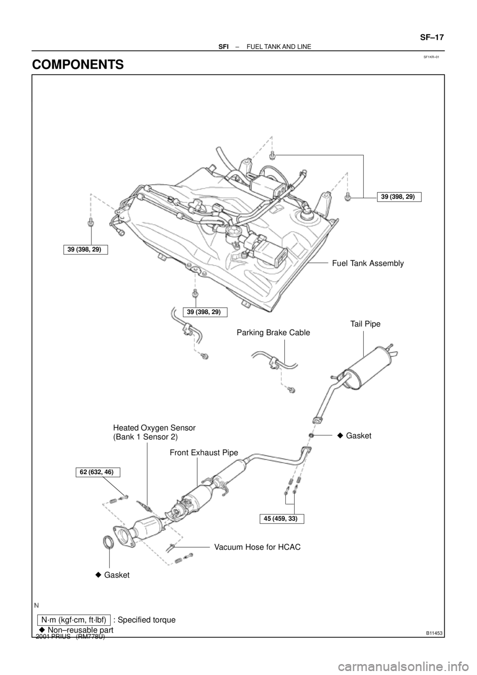
SF1KR±01
B11453
N´m (kgf´cm, ft´lbf)
� Non±reusable part: Specified torque� Gasket
Fuel Tank Assembly
Tail Pipe
39 (398, 29)
� Gasket
Front Exhaust Pipe
45 (459, 33)
39 (398, 29)
39 (398, 29)
Parking Brake Cable
62 (632, 46)
Vacuum Hose for HCAC Heated Oxygen Sensor
(Bank 1 Sensor 2)
± SFIFUEL TANK AND LINE
SF±17
2001 PRIUS (RM778U)
COMPONENTS
Page 1563 of 1943
B11454
39.2 (400, 29)39.2 (400, 29)
VSV for Purge Flow
Switching Valve
Vapor Pressure
Sensor
Charcoal
Canister
Fuel Tank
Canister Closed
Valve
Fresh Air ValveTrap Filter
N´m (kgf´cm, ft´lbf) : Specified torque SF±18
± SFIFUEL TANK AND LINE
2001 PRIUS (RM778U)
Page 1564 of 1943

2 (M+)
SF±24
± SFITHROTTLE BODY
1238 Author�: Date�:
2001 PRIUS (RM778U)
THROTTLE BODY
ON±VEHICLE INSPECTION
1. INSPECT SYSTE")
SF1KS±01
F12396
TOYOTA Hand±Held
Tester
DLC3
B11458
Ohmmeter1 (M±)
2 (M+)
SF±24
± SFITHROTTLE BODY
1238 Author�: Date�:
2001 PRIUS (RM778U)
THROTTLE BODY
ON±VEHICLE INSPECTION
1. INSPECT SYSTEM OPERATION
(a) Disconnect the throttle control motor connector.
(b) Turn the ignition switch ON.
(c) Inspect the throttle position sensor function.
(1) Connect the TOYOTA hand±held tester to the
DLC3.
(2) When turning the throttle linkage to the full open
position, check that the throttle valve opening per-
centage (THROTTLE POS) of the CURRENT DATA
shows the standard value.
Throttle valve opening percentage: 60 % or more
If operation is not as specified, check that the throttle position
sensor, wiring and ECM.
(d) Connect the throttle control motor connector.
(e) Transit to the inspection mode and start the engine.
(f) Allow the engine to warm up to normal operating tempera-
ture.
(g) To check the charging rate of the HV battery, move the
shift lever to D range and check that the engine stops.
If it does not stop, the charging rate may be low. With the shift
lever in P range, keep running the engine for a while. Then, shift
lever to D range again and check that the engine stops.
(h) Start the engine.
(i) Turn the A/C switch ON and OFF, and check the idle
speed.
Idle speed (Transmission in neutral):
1,000 ± 50 rpm (A/C OFF)
1,200 ± 50 rpm (A/C ON)
NOTICE:
Perform inspection under condition without electrical load.
(j) Stop the engine and disconnect TOYOTA hand±held tes-
ter from the DLC3.
2. INSPECT THROTTLE CONTROL MOTOR
(a) Disconnect the throttle control motor connector.
(b) Using an ohmmeter, measure the resistance between ter-
minal M+ and M±.
Resistance: 0.3 ± 100 W at 20°C (68°F)
If the resistance is not as specified, replace the throttle body.
Page 1565 of 1943
B11459
OhmmeterE2
VC
± SFITHROTTLE BODY
SF±25
1239 Author�: Date�:
2001 PRIUS (RM778U)
(c) Reconnect the throttle control motor connector.
3. INSPECT THROTTLE POSITION SENSOR
(a) Disconnect the throttle position sensor connector.
(b) Using an ohmmeter, measure the resistance between ter-
minals VC and E2.
Resistance: 1.2 ± 3.2 kW at 20°C (68°F)
If the resistance is not as specified, replace the throttle position
sensor. (See page SF±29)
(c) Reconnect the throttle position sensor connector.
4. INSPECT ACCELERATOR PEDAL POSITION SEN-
SOR (See page SF±59)
Page 1566 of 1943
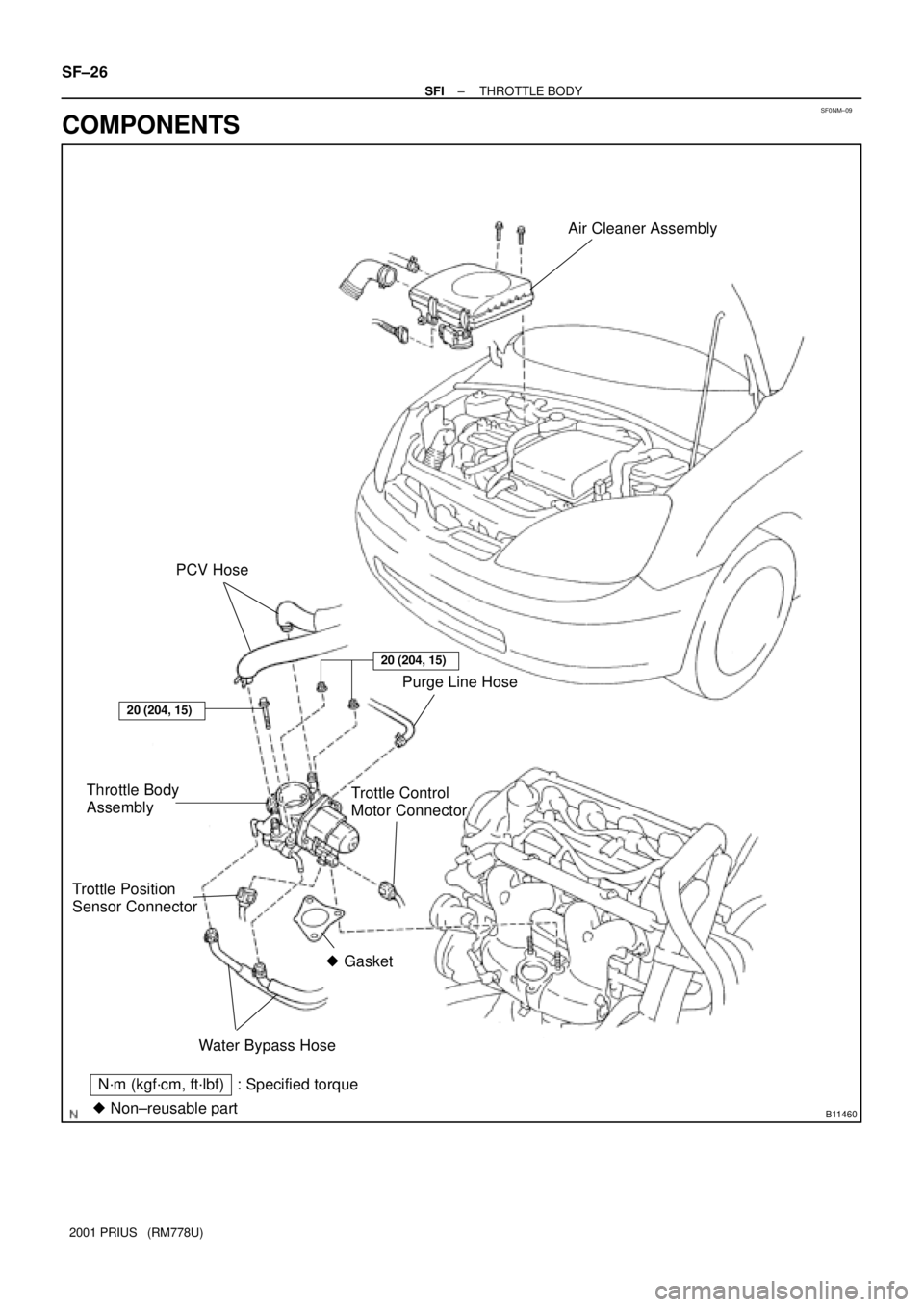
SF0NM±09
B11460
Air Cleaner Assembly
PCV Hose
Purge Line Hose
Throttle Body
AssemblyTrottle Control
Motor Connector
Water Bypass Hose Trottle Position
Sensor Connector
� Gasket
N´m (kgf´cm, ft´lbf)
� Non±reusable part: Specified torque
20 (204, 15)
20 (204, 15)
SF±26
± SFITHROTTLE BODY
2001 PRIUS (RM778U)
COMPONENTS

Heated Oxygen Sensor
(Bank 1 Sensor 2) Fuel Tank
Air Cleaner
Throttle Valve
Pressure Sensor
for HCAC
Check
Valv")

39.2 (400, 29)
VSV for Purge Flow
Switching Valve
Vapor Pressure
Sensor
Charcoal
Canister
Fuel Tank
Canister Closed
Valve
Fresh Air ValveTrap Filter
N´m (kgf´cm, ft´lbf) :")