Page 1506 of 1943

16. INSTALL INTAKE MANIFOLD
Install a new gasket, the intake manifold and 2 brackets with the
2 bolts and 2 nuts. Un")
A13935
A13934
A13907
EM±48
± ENGINE MECHANICALCYLINDER HEAD
2001 PRIUS (RM778U)
16. INSTALL INTAKE MANIFOLD
Install a new gasket, the intake manifold and 2 brackets with the
2 bolts and 2 nuts. Uniformly tighten the bolts and nuts in sever-
al passes.
Torque: 20 N´m (204 kgf´cm, 15 ft´lbf)
17. CONNECT ENGINE WIRE TO CYLINDER HEAD
(a) Install the engine wire protector to the cylinder head cover
with the 2 bolts.
(b) Connect the water ECT sensor connector.
(c) Connect the camshaft position sensor connector.
(d) Connect the oil control valve connector.
(e) Connect the 4 injector connectors.
18. INSTALL THROTTLE BODY
(See page SF±31)
19. INSTALL PCV HOSES
20. INSTALL SPARK PLUGS
(See page IG±1)
21. INSTALL IGNITION COILS (See page IG±7)
22. INSTALL AIR CLEANER ASSEMBLY
(a) Install the air cleaner assembly with the 2 bolts.
(b) Tighten the 2 hose clamps.
(c) Connect the EVAP hose to the air cleaner case.
(d) Connect the MAF meter connector.
23. INSTALL CONVERTER AND INVERTER ASSEMBLY
(See page HV±18)
24. INSTALL OUTER FR COWL TOP PANEL ASSEMBLY
(See page BO±32)
25. FILL WITH ENGINE COOLANT
26. FILL WITH HV COOLANT
27. INSTALL ENGINE UNDER COVERS
28. CONNECT BATTERY NEGATIVE (±) TERMINAL AND
HV BATTERY SERVICE PLUG (See page HV±1)
Page 1511 of 1943

REMOVAL
1. DISCONNECT BATTERY NEGATIVE (±) TERMINAL
AND HV BATTERY SERVICE PLUG
(See page HV±1)
2. REMOVE OUTER F")
EM1J0±02
A13907
A13943
± ENGINE MECHANICALENGINE UNIT
EM±53
2001 PRIUS (RM778U)
REMOVAL
1. DISCONNECT BATTERY NEGATIVE (±) TERMINAL
AND HV BATTERY SERVICE PLUG
(See page HV±1)
2. REMOVE OUTER FRONT COWL TOP PANEL AS-
SEMBLY (See page BO±32)
3. DRAIN HV COOLANT (See page HT±8)
4. DRAIN ENGINE COOLANT
5. REMOVE CONVERTER AND INVERTER ASSEMBLY
(See page HV±18)
6. REMOVE HEATER UNIT WATER PUMP
(See page AC±55)
7. REMOVE AIR CLEANER ASSEMBLY
(a) Disconnect the MAF meter connector.
(b) Disconnect the EVAP hose from the air cleaner case.
(c) Loosen the 2 hose clamps.
(d) Remove the 2 bolts and air cleaner assembly.
8. DISCONNECT CONNECTORS, CLAMPS AND HOSES
(a) Disconnect the engine wire clamps.
(b) Disconnect the heated oxygen sensor connector.
(c) Disconnect the 2 power steering connectors.
(d) Disconnect the VSV connector for purge line.
(e) Disconnect the VSV hose for purge line.
(f) Disconnect the ground strap from RH fender apron.
(g) Disconnect the ground strap from LH fender apron.
9. REMOVE AIR INLET
10. REMOVE ENGINE COOLANT RESERVOIR TANK
11. DISCONNECT 2 RADIATOR HOSES FROM RADIATOR
12. DISCONNECT HEATER HOSE FROM CYLINDER
BLOCK
Page 1512 of 1943

13. DISCONNECT SHIFT LEVER CABLE
14. REMOVE BRAKE RESERVOIR TANK
(a) Disconnect the brake fluid level se")
A13908
A13938
A13909
I18009
A13932
EM±54
± ENGINE MECHANICALENGINE UNIT
2001 PRIUS (RM778U)
13. DISCONNECT SHIFT LEVER CABLE
14. REMOVE BRAKE RESERVOIR TANK
(a) Disconnect the brake fluid level sensor connector.
(b) Remove the 2 bolts and remove the reservoir tank and
suspend it.
15. DISCONNECT ENGINE WIRE FROM CABIN
(a) Remove the ECM (See page SF±63).
(b) Disconnect the grommet from the cowl panel, and pull out
the engine wire.
16. REMOVE J/B NO. 1 FROM RH FENDER APRON
17. DISCONNECT FUEL TUBE
Disconnect the fuel tube from the fuel pump.
18. REMOVE DRIVE BELT
19. REMOVE ENGINE UNDER COVERS
20. REMOVE A/C COMPRESSER
(a) Disconnect the A/C compresser connector.
(b) Remove the 4 bolts and disconnect the A/C compresser
from the engine.
HINT:
Suspend the A/C compresser securely.
21. DISCONNECT INTERMEDIATE EXTENSION FROM
STEERING ASSEMBLY (See page SR±6)
22. REMOVE EXHAUST PIPE
(a) Disconnect the heated oxygen sensor from the exhaust
pipe.
(b) Remove the 2 springs and 3 bolts.
(c) Disconnect the 2 O±rings, and remove the exhaust pipe
and 2 gaskets.
Page 1517 of 1943

12. INSTALL EXHAUST PIPE
(a) Install the 2 gaskets to the exhaust pipe and connect the
2 O±rings.
(b) Install")
A13939
I18009
A13909
A13938
EM±60
± ENGINE MECHANICALENGINE UNIT
2001 PRIUS (RM778U)
12. INSTALL EXHAUST PIPE
(a) Install the 2 gaskets to the exhaust pipe and connect the
2 O±rings.
(b) Install the 2 springs and 3 bolts.
Torque:
Front exhaust pipe: 62 N´m (630 kgf´cm, 46 ft´lbf)
Tailpipe: 32 N´m (326 kgf´cm, 24 ft´lbf)
(c) Connect the hose to the actuator.
(d) Connect the heated oxygen sensor.
13. INSTALL A/C COMPRESSER
(a) Connect the A/C compresser to the engine with the 4
bolts.
Torque: 25 N´m (255 kgf´cm, 18 ft´lbf)
(b) Connect the A/C compresser connector.
14. CONNECT INTERMEDIATE EXTENSION STEERING
ASSEMBLY (See page SR±14)
15. INSTALL DRIVE BELT (See page SA±23)
16. CONNECT FUEL TUBE
17. INSTALL J/B NO. 1 TO RH FENDER APRON
18. CONNECT ENGINE WIRE TO CABIN
(a) Pull in the engine wire to the cowk panel and connect the
grommet.
(b) Connect the ECM connectors.
(c) Install the ECM (See page SF±63).
19. INSTALL BRAKE RESERVOIR TANK
(a) Install the reservoir tank with the 2 bolts.
(b) Connect the brake fluid level sensor connector.
20. CONNECT SHIFT LEVER CABLE TO TRANSAXLE
21. CONNECT HEATER HOSE TO CYLINDER BLOCK
22. CONNECT 2 RADIATOR HOSES TO RADIATOR
23. INSTALL ENGINE COOLANT RESERVOIR TANK
24. INSTALL AIR INLET
Page 1518 of 1943

25. CONNECT CONNECTORS, CLAMPS AND HOSES
(a) Connect the Ground strap from LH fender apron.
(b) Connect the Ground strap from")
A13943
A13907
± ENGINE MECHANICALENGINE UNIT
EM±61
2001 PRIUS (RM778U)
25. CONNECT CONNECTORS, CLAMPS AND HOSES
(a) Connect the Ground strap from LH fender apron.
(b) Connect the Ground strap from RH fender apron.
(c) Connect the VSV hose for purge line.
(d) Connect the VSV connector for purge line.
(e) Connect the 2 power steering connectors.
(f) Connect the Heated oxygen sensor connector.
(g) Connect the Engine wire clamps.
26. INSTALL AIR CLEANER ASSEMBLY
(a) Install the air cleaner assembly with the 2 bolts.
(b) Tighten the 2 hose clamps.
(c) Connect the EVAP hose to the air cleaner case.
(d) Connect the MAF meter connector.
27. INSTALL HEATER UNIT WATER PUMP
(See page AC±55)
28. INSTALL CONVERTER AND INVERTER ASSEMBLY
(See page HV±22)
29. INSTALL OUTER FR COWL TOP PANEL ASSEMBLY
(See page BO±35)
30. FILL WITH ENGINE COOLANT
31. FILL WITH HV COOLANT
32. INSTALL ENGINE UNDER COVERS
33. CONNECT BATTERY NEGATIVE (±) TERMINAL AND
HV BATTERY SERVICE PLUG (See page HV±1)
34. ROAD TEST VEHICLE
Check for abnormal noiss, shock slippage, correct shift points
and smooth operation.
35. RECHECK ENGINE COOLANT AND HV TRANSAXLE
COOLANT
Page 1519 of 1943
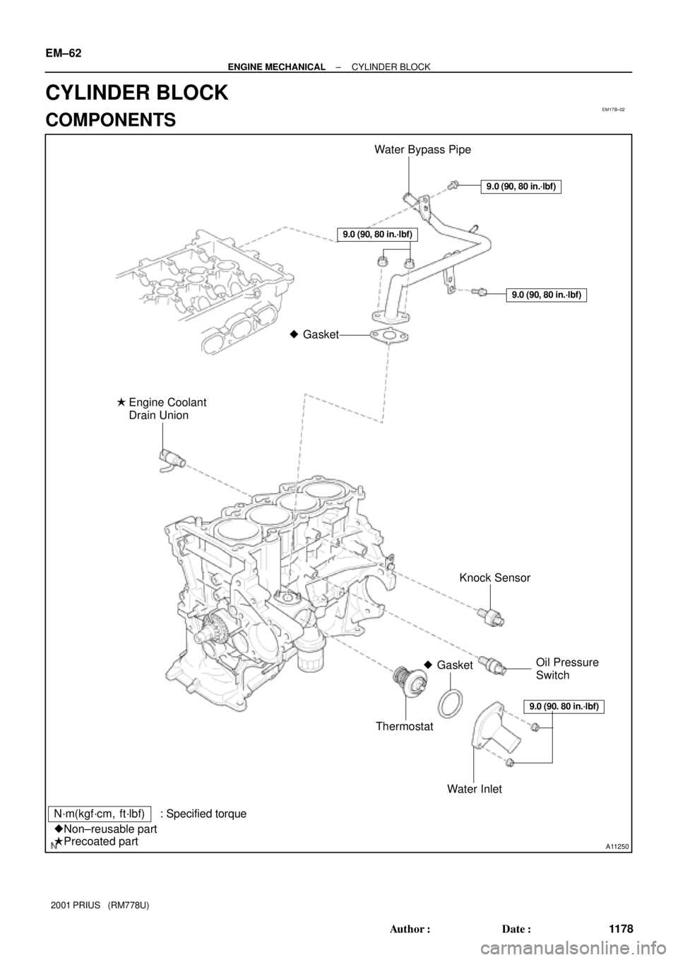
EM17B±02
A11250
Water Bypass Pipe
Knock Sensor
Thermostat
Water Inlet Engine Coolant
Drain Union
�
N´m(kgf´cm, ft´lbf) : Specified torque
�Non±reusable part
�Precoated part
Gasket
�
�GasketOil Pressure
Switch
9.0 (90, 80 in.´lbf)
9.0 (90, 80 in.´lbf)
9.0 (90. 80 in.´lbf)
9.0 (90, 80 in.´lbf)
EM±62
± ENGINE MECHANICALCYLINDER BLOCK
1178 Author�: Date�:
2001 PRIUS (RM778U)
CYLINDER BLOCK
COMPONENTS
Page 1521 of 1943

DISASSEMBLY
1. INSTALL ENGINE TO ENGINE STAND FOR
DISASSEMBLY
2. REMOVE TIMING CHAIN (See page EM�")
EM17C±04
A10451
A11268
A11269
A14342
EM±64
± ENGINE MECHANICALCYLINDER BLOCK
2001 PRIUS (RM778U)
DISASSEMBLY
1. INSTALL ENGINE TO ENGINE STAND FOR
DISASSEMBLY
2. REMOVE TIMING CHAIN (See page EM±15)
3. REMOVE CYLINDER HEAD
(See page EM±29)
4. REMOVE ENGINE WIRE
5. REMOVE WATER BYPASS PIPE
Remove the 2 nuts, bolt and water bypass pipe.
6. REMOVE THERMOSTAT
(See page CO±10)
7. REMOVE KNOCK SENSOR (See page SF±56)
8. REMOVE OIL PRESSURE SWITCH
(See page LU±1)
9. REMOVE ENGINE COOLANT DRAIN UNION
10. REMOVE OIL FILTER
(See page LU±3)
11. REMOVE OIL FILTER UNION
Using a 12 mm hexagon wrench, remove the oil filter union.
12. REMOVE OIL PAN NO. 2
(a) Remove the 9 bolts and 2 nuts.
(b) Insert the blade of SST between the oil pan No. 1 and oil
pan No. 2, and cut off applied sealer and remove the oil
pan.
SST 09032±00100
NOTICE:
�Be careful not to the damage the oil pan contact sur-
face of the oil pan No. 1.
�Be careful not to damage the oil pan No. 2 flange.
13. REMOVE OIL STRAINER
Remove the bolt and 2 nuts, oil strainer and gasket.
Page 1539 of 1943
P12477
Adhesive
A10451
± ENGINE MECHANICALCYLINDER BLOCK
EM±83
2001 PRIUS (RM778U)
18. INSTALL ENGINE COOLANT DRAIN UNION
(a) Apply adhesive to 2 or 3 threads.
Adhesive:
Part No. 08833±00080, THREE BOND 1344,
LOCTITE 242 or equivalent
(b) Install the drain union.
Torque: 35 N´m (350 kgf´cm, 25 ft´lbf)
HINT:
After applying the specified torque, rotate the drain union clock-
wise until its drain port is facing downward.
19. INSTALL KNOCK SENSOR
Torque: 39 N´m (400 kgf´cm, 29 ft´lbf)
20. INSTALL OIL PRESSURE SWITCH
(See page LU±1)
21. INSTALL THERMOSTAT
(See page CO±12)
22. INSTALL WATER BYPASS PIPE
Torque: 9.0 N´m (92 kgf´cm, 80 in.´lbf)
23. INSTALL ENGINE WIRE
24. INSTALL CYLINDER HEAD
(See page EM±45)
25. INSTALL TIMING SPROCKETS AND TIMING CHAIN
(See page EM±21)
26. REMOVE ENGINE STAND

18. INSTALL ENGINE COOLANT DRAIN UNION
(a) Apply adhesive to 2 or 3 threads.
Adhesive:
Part No. 08833±00080, THR")