Page 1476 of 1943

REMOVAL
1. DISCONNECT BATTERY NEGATIVE (±) TERMINAL
AND HV BATTERY SERVICE PLUG
(See page HV±1)
2")
EM1IU±03
A13907
A13908
A13934
A13943
± ENGINE MECHANICALTIMING CHAIN
EM±15
2001 PRIUS (RM778U)
REMOVAL
1. DISCONNECT BATTERY NEGATIVE (±) TERMINAL
AND HV BATTERY SERVICE PLUG
(See page HV±1)
2. REMOVE OUTER FR COWL TOP PANEL ASSEMBLY
(See page BO±32)
3. REMOVE RH ENGINE UNDER COVER
4. DRAIN ENGINE COOLANT
5. REMOVE AIR CLEANER ASSEMBLY
(a) Disconnect the MAF meter connector.
(b) Disconnect the EVAP hose from the air cleaner case.
(c) Loosen the 2 hose clamps.
(d) Remove the 3 bolts and air cleaner assembly.
6. REMOVE BRAKE RESERVOIR TANK
(a) Disconnect the brake fluid level sensor connector.
(b) Remove the 2 bolts and remove the reservoir tank and
suspend it.
(c) Remove the 3 bolts and reservoir tank bracket.
7. DISCONNECT CONNECTORS
(a) Disconnect the 4 ignition connectors.
(b) Disconnect the 4 injector connectors.
(c) Disconnect the 2 VSV connectors.
(d) Disconnect the camshaft position sensor connector.
(e) Disconnect the water temperature connector.
(f) Disconnect the Camshaft timing oil control valve connec-
tor.
8. REMOVE AIR INLET
9. REMOVE ENGINE COOLANT RESERVOIR TANK
10. REMOVE VSV FROM ENGINE MOUNTING INSULA-
TOR
11. REMOVE DRIVE BELT
Page 1478 of 1943

(b) Check that both timing marks on the camshaft timing
sprocket and valve tim")
A11245
Timing Marks
A11253
SST
SST
A11254
SST
A11258
A11255
± ENGINE MECHANICALTIMING CHAIN
EM±17
2001 PRIUS (RM778U)
(b) Check that both timing marks on the camshaft timing
sprocket and valve timing controller assembly are facing
right up as shown in the illustration.
If not, turn the crankshaft 1 revolution (360°) and align the
marks as above.
16. REMOVE CRANKSHAFT PULLEY
(a) Using SST, remove the pulley bolt.
SST 09213±70010, 09330±00021
(b) Remove the crankshaft pulley and pin.
HINT:
If necessary, remove the pulley with SST.
SST 09950±50012 (09951±05010, 09952±05010,
09953±05020, 09954±05020)
17. REMOVE CRANKSHAFT POSITION SENSOR
(See page IG±12)
18. REMOVE RH ENGINE MOUNTING BRACKET
Remove the 4 bolts and mounting bracket.
19. REMOVE WATER PUMP (See page CO±6)
20. REMOVE OIL CONTROL VALVE (See page EM±29)
21. REMOVE TIMING CHAIN COVER
(a) Remove the 13 bolts and nut.
(b) Using a torx wrench socket (E8), remove the stud bolt.
(c) Remove the timing chain cover by prying the portions be-
tween the cylinder head and cylinder block with a screw-
driver.
NOTICE:
Be careful not to damage the contact surfaces of the timing
chain cover, cylinder head and cylinder block.
Page 1482 of 1943

(e) Install the timing chain cover, new O±ring and water pump
with the 16 bolts and 3 nuts. Uni")
A11274
A B
CE D
F
AG
G
EB
A
AA
A11258
A
B
± ENGINE MECHANICALTIMING CHAIN
EM±23
2001 PRIUS (RM778U)
(e) Install the timing chain cover, new O±ring and water pump
with the 16 bolts and 3 nuts. Uniformly tighten the bolts
and nut in several passes.
Torque:
Bolt A 11 N´m (113 kgf´cm, 8 ft´lbf)
Bolt B 24 N´m (245 kgf´cm, 18 ft´lbf)
Bolt C 11 N´m (113 kgf´cm, 8 ft´lbf)
Bolt D 24 N´m (245 kgf´cm, 18 ft´lbf)
Bolt E 11 N´m (113 kgf´cm, 8 ft´lbf)
Nut F 24 N´m (245 kgf´cm, 18 ft´lbf)
Nut G 11 N´m (113 kgf´cm, 8 ft´lbf)
NOTICE:
�Pay attention not to wrap the chain and slipper over
the chain cover seal line.
�After installing the chain cover, must install the
mounting bracket and water pump within 15 minutes.
HINT:
Each bolt length in indicated in the illustration.
A 20 mm (0.787 in.)
B 30 mm (1.181 in.)
C 35 mm (1.378 in.)
D 20 mm (0.787 in.)
E 35 mm (1.378 in.)
4. INSTALL RH ENGINE MOUNTING BRACKET
(a) Apply seal packing to threads of the mounting bolt.
Seal packing:
Part No. 08826 ± 00080 or equivalent
HINT:
Do not apply seal packing to 2 or 3 threads of the bolt end.
(b) Install the mounting bracket with the 4 bolts.
Torque: 55 N´m (561 kgf´cm, 41 ft´lbf)
5. INSTALL CRANKSHAFT POSITION SENSOR
Torque:
Bolt A 7.5 N´m (76 kgf´cm, 66 in.´lbf)
Bolt B 11 N´m (113 kgf´cm, 8 ft´lbf)
6. INSTALL OIL CONTROL VALVE (See page EM±45)
Torque: 7.5 N´m (76 kgf´cm, 66 in.´lbf)
Page 1484 of 1943
A13934
A13907
± ENGINE MECHANICALTIMING CHAIN
EM±25
2001 PRIUS (RM778U)
16. CONNECT CONNECTORS
(a) Connect the Camshaft timing oil control valve connector.
(b) Connect the water temperature sensor connector.
(c) Connect the camshaft position sensor connector.
(d) Connect the 2 VSV connectors.
(e) Connect the 4 injector connectors.
(f) Connect the 4 ignition connectors.
17. INSTALL AIR CLEANER ASSEMBLY
(a) Install the air cleaner assembly with the 2 bolts.
(b) Tighten the 2 hose clamps.
(c) Connect the EVAP hose to the air cleaner case.
(d) Connect the MAF meter connector.
18. INSTALL BRAKE RESERVOIR TANK
19. INSTALL OUTER FR COWL TOP PANEL ASSEMBLY
(See page BO±35)
20. FILL WITH ENGINE COOLANT
21. INSTALL ENGINE UNDER COVERS
22. CONNECT BATTERY NEGATIVE (±) TERMINAL AND
HV BATTERY SERVICE PLUG (See page HV±1)
23. ROAD TEST VEHICLE
Check for abnormal noises, shock slippage, correst shift points
and smooth operation.
24. RECHECK ENGINE COOLANT AND HV TRANSAXLE
COOLANT
Page 1486 of 1943
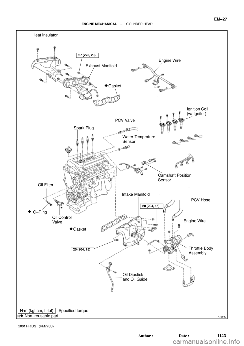
A13930
N´m (kgf´cm, ft´lbf)
� Non±reusable part: Specified torque Heat Insulator
Exhaust Manifold
Ignition Coil
(w/ Igniter)
PCV Valve
Water Temprature
Sensor
Camshaft Position
Sensor
Engine Wire
Oil Dipstick
and Oil GuideThrottle Body
Assembly O±Ring �
Gasket
�
Engine Wire
Gasket �
27 (275, 20)
Oil Filter
20 (204, 15)
PCV Hose
Oil Control
Valve
20 (204, 15)
Intake Manifold
Spark Plug
± ENGINE MECHANICALCYLINDER HEAD
EM±27
1143 Author�: Date�:
2001 PRIUS (RM778U)
Page 1488 of 1943

REMOVAL
1. DISCONNECT BATTERY NEGATIVE (± )TERMINAL
AND HV BATTERY SERVICE PLUG
(See page HV±1)
2. REMOV")
EM1IX±02
A13907
B11761
A13934
± ENGINE MECHANICALCYLINDER HEAD
EM±29
2001 PRIUS (RM778U)
REMOVAL
1. DISCONNECT BATTERY NEGATIVE (± )TERMINAL
AND HV BATTERY SERVICE PLUG
(See page HV±1)
2. REMOVE OUTER FRONT COWL TOP PANEL AS-
SEMBLY (See page BO±32)
3. DRAIN HV TRANSAXLE COOLANT
(See page HT±6)
4. DRAIN ENGINE COOLANT
5. REMOVE CONVERTER AND INVERTER ASSEMBLY
(See page HV±18)
6. REMOVE AIR CLEANER ASSEMBLY
(a) Disconnect the MAF meter connector.
(b) Disconnect the EVAP hose from the air cleaner case.
(c) Loosen the 2 hose clamps.
(d) Remove the 3 bolts and air cleaner assembly.
7. REMOVE IGNITION COILS (See page IG±6)
8. REMOVE SPARK PLUGS (See page IG±1)
9. REMOVE PCV HOSES
10. REMOVE THROTTLE BODY (See page SF±28)
11. DISCONNECT ENGINE WIRE FROM CYLINDER HEAD
(a) Disconnect the ECT sensor connector.
(b) Disconnect the camshaft position sensor connector.
(c) Disconnect the oil control valve connector.
(d) Disconnect the 4 injector connectors.
(e) Remove the 3 bolts and disconnect the engine wire pro-
tector from the cylinder head cover.
Page 1489 of 1943

12. REMOVE INTAKE MANIFOLD
Remove the 3 bolts, 2 nuts intake manifold and gasket.
13. DISCONNECT FRONT EXHAUS")
A13935
A13932
A11226
A13933
EM±30
± ENGINE MECHANICALCYLINDER HEAD
2001 PRIUS (RM778U)
12. REMOVE INTAKE MANIFOLD
Remove the 3 bolts, 2 nuts intake manifold and gasket.
13. DISCONNECT FRONT EXHAUST PIPE FROM EX-
HAUST MANIFOLD
(a) Remove the 2 bolts and 2 springs holding the front ex-
haust pipe to the exhaust manifold.
(b) Remove the gasket.
14. REMOVE EXHAUST MANIFOLD STAY
Remove the 3 bolts and exhaust manifold stay.
15. REMOVE EXHAUST MANIFOLD
(a) Remove the 4 bolts and upper heat insulator.
(b) Remove the 3 bolts 2 nuts, exhaust manifold and gasket.
16. REMOVE CAMSHAFT POSITION SENSOR
17. REMOVE ECT SENSOR
18. REMOVE OIL CONTROL VALVE
19. REMOVE PCV VALVE
20. REMOVE OIL FILLER CAP
21. REMOVE HEAD COVER (See page EM±15)
22. REMOVE INJECTOR (See page SF±11)
23. REMOVE TIMING CHAIN COVER (See page EM±15)
24. REMOVE CAMSHAFT TIMING SPROCKET AND
VALVE TIMING CONTROL ASSEMBLY
Hold the hexagonal head portion of the camshaft with a wrench,
and remove the 2 bolts and timing sprocket and valve timing
controller assembly.
NOTICE:
�Be careful not to damage the cylinder head and valve
lifter with the wrench.
Page 1505 of 1943

(d) Temporarily install the timing sprocket bolt.
(e) Hold the hexagon head portion of the camshaft with a
wrench, a")
A13933
A11226
A13932
± ENGINE MECHANICALCYLINDER HEAD
EM±47
2001 PRIUS (RM778U)
(d) Temporarily install the timing sprocket bolt.
(e) Hold the hexagon head portion of the camshaft with a
wrench, and install the bolt.
Torque: 64 N´m (650 kgf´cm, 47 ft´lbf)
5. CHECK AND ADJUST VALVE CLEARANCE
(See page EM±5)
6. INSTALL CYLINDER HEAD COVER
(See page EM±21)
7. INSTALL OIL CONTROL VALVE
8. INSTALL OIL FILTER CAP
9. INSTALL PCV VALVE
10. INSTALL ECT SENSOR
(See page SF±49)
11. INSTALL CAMSHAFT POSITION SENSOR
(See page IG±10)
12. INSTALL TIMING CHAIN COVER
(See page EM±21)
13. INSTALL EXHAUST MANIFOLD
(a) Install a new gasket and the exhaust manifold with the 3
bolts 2 nuts. Uniformly tighten the bolts and nuts in sever-
al passes.
Torque: 27 N´m (275 kgf´cm, 20 ft´lbf)
(b) Install the upper heat insulator with the 4 bolts.
Torque: 8.0 N´m (82 kgf´cm, 71 in.´lbf)
14. INSTALL EXHAUST MANIFOLD STAY
Install the manifold stay with the 3 bolts. Alternately tighten the
bolts.
Torque: 37 N´m (377 kgf´cm, 27 ft´lbf)
15. CONNECT FRONT EXHAUST PIPE TO EXHAUST
MANIFOLD
(a) Place a new gasket to the exhaust manifold.
(b) Install the 2 bolts and 2 springs holding the front exhaust
pipe to the exhaust manifold.
Torque: 62 N´m (630 kgf´cm, 46 ft´lbf)

16. CONNECT CONNECTORS
(a) Connect the Camshaft timing oil control valve connector.
(b) Connect the water temperature sens")