Page 749 of 1943
A14062
± DIAGNOSTICSENGINE
DI±151
2001 PRIUS (RM778U)
2 Check operation of OCV.
PREPARATION:
(a) Start the engine and warmed it up.
(b) Disconnect the OCV connector.
(c) Apply battery positive voltage between terminals of the
OCV.
CHECK:
Check the engine speed.
OK:
Rough idle or engine stalled.
NG Replace OCV.
OK
3 Check voltage between terminals OCV+ and OCV± of ECM connector
(See page DI±121).
NG Check and replace ECM (See page IN±41).
OK
4 Check for open and short in harness and connector between OCV and ECM
(See page IN±41).
NG Repair or replace.
OK
Check for intermitent problems
(See page DI±3).
Page 750 of 1943
A14062
DI±152
± DIAGNOSTICSENGINE
2001 PRIUS (RM778U)
OBD II scan tool (excluding TOYOTA hand±held tester)
1 Check operation of OCV.
PREPARATION:
(a) Start the engine and warmed it up.
(b) Disconnect the OCV connector.
(c) Apply battery positive voltage between terminals of the
OCV.
CHECK:
Check the engine speed.
OK:
Rough idle or engine stalled
NG Replace OCV.
OK
2 Check voltage between terminals OCV+ and OCV± of ECM connector
(See page DI±121).
NG Check and replace ECM (See page IN±41).
OK
3 Check for open and short in harness and connector between OCV and ECM
(See page IN±41).
NG Repair or replace.
OK
Check for intermitent problems
(See page DI±3).
Page 754 of 1943
A14058
ECM
+B 4
E8
BatteryW±RG±R
MREL 25 EFI Relay
I15 Ignition
SW EFI
IGSW 6
IE 1B35
AM2E9
J24 J25
J1
J/CE10 B
9 3
B
2C1 2
2G
24
A F121 3
1K 1F12 1A
1J 2
7 1
W±BW±R
B±W
B±G Engine Room J/B
F18
FL
Block
No. 2IA2
FL Block No. 19G±R
J7
J/C
B±W AM2 IG2
J/C Instrument
Panel J/B
F13 1
A
A W±BCB
MAIN
1 DI±156
± DIAGNOSTICSENGINE
2001 PRIUS (RM778U)
ECM Power Source Circuit
CIRCUIT INSPECTION
When the ignition switch is turned on, battery positive voltage is applied to IG2 Relay, terminal IGSW of the
ECM and the EFI main relay (Marking: EFI MAIN) control circuit in the ECM sends a signal to terminal MREL
of the ECM switching on the EFI main relay.
This signal causes current to flow to the coil, closing the contacts of the EFI main relay and supplying power
to terminals +B of the ECM.
If the ignition switch is turned off, the ECM continues to switch on the EFI main relay for a maximum of 2
seconds for the initial setting of the IAC valve.
WIRING DIAGRAM
DI7DK±02
Page 756 of 1943
A13630
Engine Room J/B
AM2 Fuse
DI±158
± DIAGNOSTICSENGINE
2001 PRIUS (RM778U)
4 Check AM2 fuse.
PREPARATION:
Remove the AM2 fuse from the engine room J/B.
CHECK:
Check the continuity of the AM2 fuse.
OK:
Continuity
NG Check for short in all harness and components
connected to AM2 fuse (See attached wiring dia-
gram).
OK
5 Check ignition switch (See page BE±16).
NG Replace ignition switch.
OK
Check and repair harness and connector be-
tween battery and ignition switch, and igni-
tion switch and ECM.
Page 758 of 1943
DI±160
± DIAGNOSTICSENGINE
2001 PRIUS (RM778U)
9 Check for open and short in harness and connector between terminal MREL of
ECM and body ground (See page IN±41).
NG Repair or replace harness or connector.
OK
Check and repair harness or connector be-
tween EFI1 fuse and battery.
Page 759 of 1943

A14059
B±G
EFICIR OPN
Relay
MREL Engine Room J/B
1A
B
AECM
FC
F16
Fuel
Pump
IE 5
FL Block No. 1
MAIN
F12
BatteryE8
E9 259
W±B
J17
J/C J1
J/C
IG J7
J/C IA1
IA2
W±B
AA A W±B G±R B±R
F18
FL Block No. 2EFI
Relay
1K 1F
1B10
1F
2 121
3
2
1
3
3
1
11 52 1
3
F13G±R
B±R
7 14
4
G±R
± DIAGNOSTICSENGINE
DI±161
2001 PRIUS (RM778U)
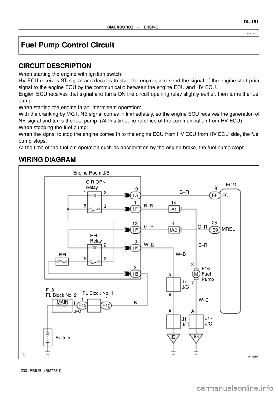
Fuel Pump Control Circuit
CIRCUIT DESCRIPTION
When starting the engine with ignition switch:
HV ECU receives ST signal and decides to start the engine, and send the signal of the engine start prior
signal to the engine ECU by the communicatio between the engine ECU and HV ECU.
Engien ECU receives that signal and turns ON the circuit opening relay slightly earlier, then turns the fuel
pump.
When starting the engine in an intermittent operation:
With the cranking by MG1, NE signal comes in immediately, so the engine ECU receives the generation of
NE signal and turns the fuel pump. (At this time, no refernce of the communication from HV ECU)
When stopping the fuel pump:
When the signal to stop the engine comes in to the engine ECU from HV ECU from HV ECU side, the fuel
pump stops.
At the time of the fuel cut opetation such as deceleration by the engine brake, the fuel pump stops.
WIRING DIAGRAM
DI7T7±01
Page 764 of 1943

A14037
Combination MeterECM
Instrument Panel J/B
W
BatteryE10 IG1 Relay
6
J11
J/C IG1C11
C10
ID DC/DCG±R
2A
A 5
W
W±B
F114
3GAUGE
Ignition SW 22
2 3B±Y
21
2 1
1 1
MAINL
AM1
B±G4
FL Block No. 1FL Block No. 2 F1312D
2B 2K 2H
86 5
AM1
W±G
MIL
DI±166
± DIAGNOSTICSENGINE
2001 PRIUS (RM778U)
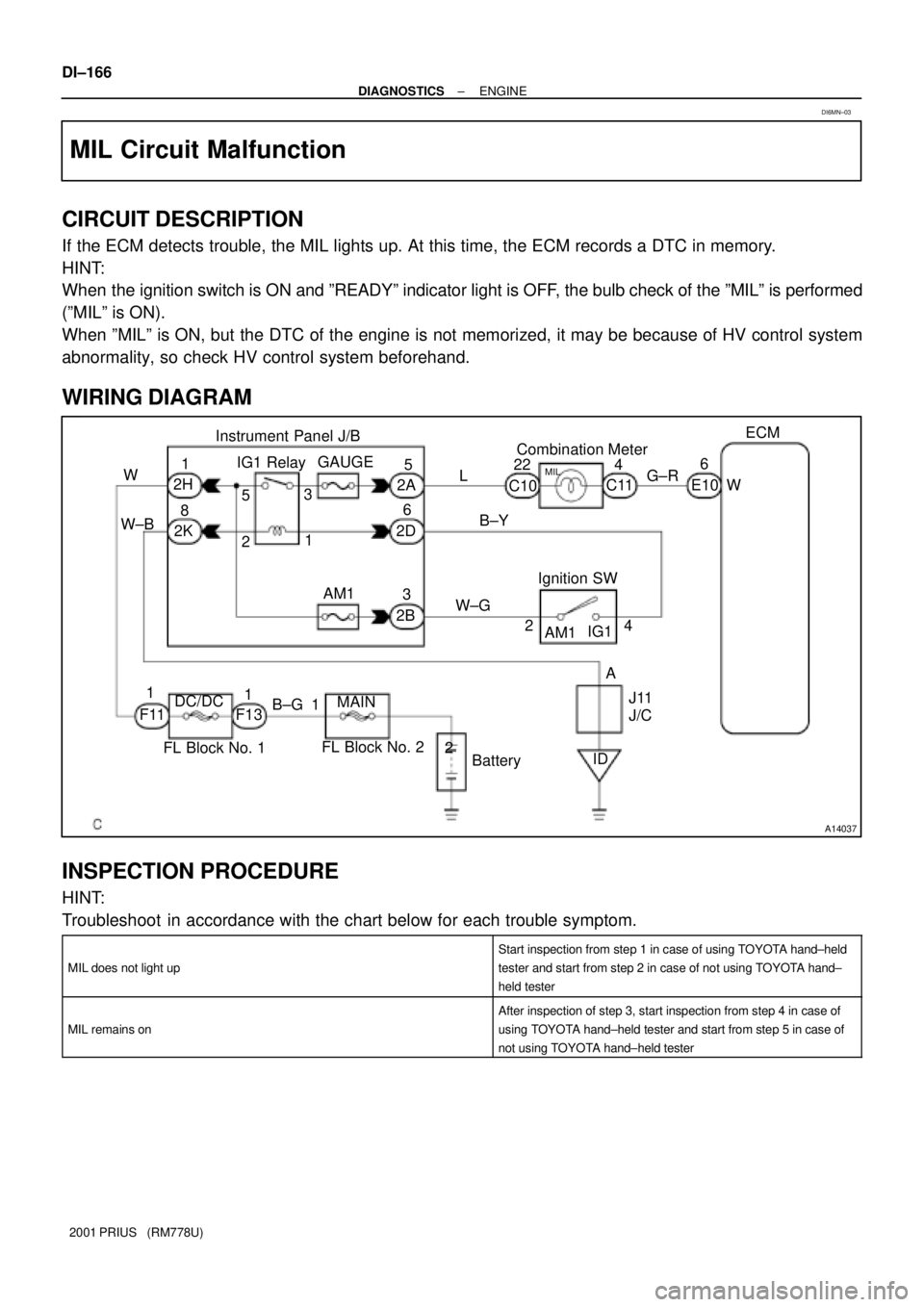
MIL Circuit Malfunction
CIRCUIT DESCRIPTION
If the ECM detects trouble, the MIL lights up. At this time, the ECM records a DTC in memory.
HINT:
When the ignition switch is ON and ºREADYº indicator light is OFF, the bulb check of the ºMILº is performed
(ºMILº is ON).
When ºMILº is ON, but the DTC of the engine is not memorized, it may be because of HV control system
abnormality, so check HV control system beforehand.
WIRING DIAGRAM
INSPECTION PROCEDURE
HINT:
Troubleshoot in accordance with the chart below for each trouble symptom.
MIL does not light up
Start inspection from step 1 in case of using TOYOTA hand±held
tester and start from step 2 in case of not using TOYOTA hand±
held tester
MIL remains on
After inspection of step 3, start inspection from step 4 in case of
using TOYOTA hand±held tester and start from step 5 in case of
not using TOYOTA hand±held tester
DI6MN±03
Page 772 of 1943

DI82J±02
Prius Problem Check Sheet
Vehicle
Specifications
Please fill in the blanks within bold frame.Name of DealerPerson in Charge at
HeadquartersPerson in Charge
at Dealer
Model CodeOffice
Vehicle Delivery Date
Frame No.
Unit No. etc.
Option . . . :
( ) Navigation (equipped by ( ) MOP ( ) dealer) ( ) Cold climate specification
( ) others( )Problem Occurrence Date
Service Entry Date NHW11±
. .
. .Registration datemiles
. .
Contents of complaint (Status when and before/after occurring in
the order of events as correct as possible)Characteristics of Customer
Gender
Age
Occupation
Vehicle used before
Main use area
Frequency in use
Others times/day or
week or month
Status of engineOthers
Interview Results
( ) Male ( ) Female
suburbs ( ) %
Others ( ) ( ) %
city area ( ) %
mountain area ( ) %
Driving ConditionRoad Condition
Vehicle Condition
Vehicle Speed
km/h
( ) when starting
( ) when according
( ) When
normal driving
( ) when
decelerating
( ) when braking
( ) when shopping
( ) when parking
( ) when turning
( ) when
ABS actuating
( ) others
( )( ) flat road
( ) up hill ( ) down
hill incline of
° /%
distance
km
( ) dry paved road
( ) wet paved road
( ) rough paved road
( ) unpaved road
( ) snowy/frozen
road
( ) bump/curb
( ) others
( )( ) when starting
( ) right after
starting
( ) until min.
after starting
( ) until min.
after starting
of driving
( ) when shopping
system
( ) while shopping
engine
( ) when starting
engine
( ) when revolving
engineHV Battery
indication
( ) 4/4 ( ) 3/4
( ) 2/4 ( ) 1/4
( ) unidentified
Shift position
(indication)
( ) P ( ) R ( ) N
( ) D ( ) B
( ) when operating
"Weather:
A/C status
( ) no indication
( ) unidentified
( ) A/C ( ) FULL
( ) OFF
( ) unidentifiedWarning light
(MIL)
( ) ON ( ) OFF
( ) PS
( ) main battery
( ) HV!
( ) engine
( ) charge
( ) output
control
( ) brake
( ) ABS
( ) others
( )
Temperature:
°C
Brake operation
( ) brake slowly
( ) Brake suddenly
( ) use two pedals
system
Frequency in
occurrence
( ) always
( ) sometimes
( ) only once
Fuel level
( ) segmentsmphOdometer Reading
mph
°F km
± DIAGNOSTICSHYBRID VEHICLE CONTROL SYSTEM
DI±175
2001 PRIUS (RM778U)
CUSTOMER PROBLEM ANALYSIS CHECK