Page 669 of 1943

A14053
Battery F13 A
B 1K
1 AM2 Engine RoomJ/B
W±R
71 1A
1E5
6Instrument
Panel J/B65
B±R
IG2
B±GR±W
B±W B±W
B±W
B±WI5
Injector No. 1
1
2C1
21
2
1 2
J1
J/C
B±W
L±W
1 9
2G
2BE8
E8
E7
E7Engine ECU
#10
#20
#30
#40 Y
11 3
I15
Ignition SW W±B1J
12
F12 A
MAIN
I6
Injector No. 2
I7
Injector No. 3
I8
Injector No. 4
1J
1B
AM2
A3
2G2
2
2
J7
J/C
B±W
B±W
B±W
B±WB±W
W±R
IG2
Relay
2 2
1 3
5
1 W±BFL Block No. 1
F18 FL Block No. 2 DI±66
± DIAGNOSTICSENGINE
2001 PRIUS (RM778U)
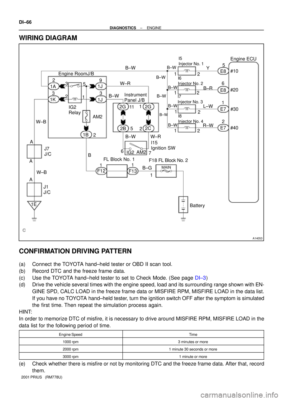
WIRING DIAGRAM
CONFIRMATION DRIVING PATTERN
(a) Connect the TOYOTA hand±held tester or OBD II scan tool.
(b) Record DTC and the freeze frame data.
(c) Use the TOYOTA hand±held tester to set to Check Mode. (See page DI±3)
(d) Drive the vehicle several times with the engine speed, load and its surrounding range shown with EN-
GINE SPD, CALC LOAD in the freeze frame data or MISFIRE RPM, MISFIRE LOAD in the data list.
If you have no TOYOTA hand±held tester, turn the ignition switch OFF after the symptom is simulated
the first time. Then repeat the simulation process again.
HINT:
In order to memorize DTC of misfire, it is necessary to drive around MISFIRE RPM, MISFIRE LOAD in the
data list for the following period of time.
Engine SpeedTime
1000 rpm3 minutes or more
2000 rpm1 minute 30 seconds or more
3000 rpm1 minute or more
(e) Check whether there is misfire or not by monitoring DTC and the freeze frame data. After that, record
them.
Page 685 of 1943

A14054
11 1A 6
1K
BR 3
1BG±R
1
2 CAIA2
32E9ECM
CCV EVP1
E2
PTNK
VC E7
LE925
2
15V2 VSV
(EVAP)4
TBP Engine Room J/B
B±R 1
1 11F
1 1EFI
Relay
3
2
112
6 B EFI
W±B
BC1
V5 VSV (Purge Flow
Switching Valve) B±G
IE A F12
MAIN
Battery1 5
7 B
BB
C B
4 3
5
2
13
1 1F13
F13
J1
J/CJ7
J/C
A AW±BMREL
29
E9
E8
E9
E818
22 G±R
J/C
J5 J4
IA1 BB19
J4J5 J5J/C
V4
Vapor Pressure
Sensor
Y±RJ8
J/C
Y±R
BC1 BC1 BC1
BC1 BC1BC1
IO1
2
2
2 V6 VSV (Canister Closed Valve)
B
C Y±R
Y±R L±R L±RBRL B±R B CA
AB
R±L
FL Block No. 1
F18
FL Block No. 2 DI±82
± DIAGNOSTICSENGINE
2001 PRIUS (RM778U)
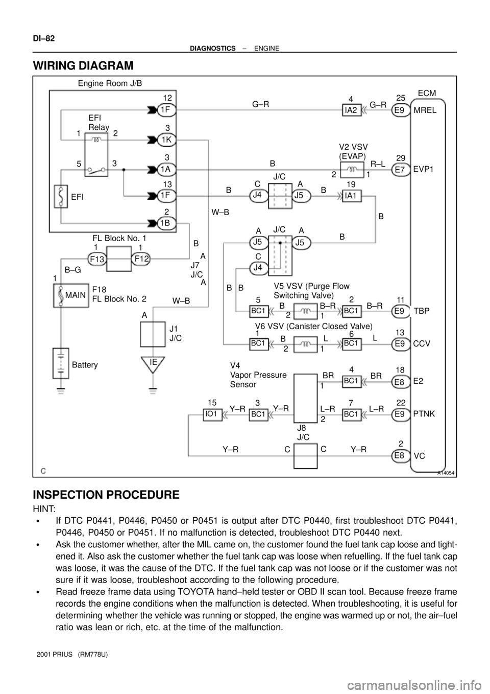
WIRING DIAGRAM
INSPECTION PROCEDURE
HINT:
�If DTC P0441, P0446, P0450 or P0451 is output after DTC P0440, first troubleshoot DTC P0441,
P0446, P0450 or P0451. If no malfunction is detected, troubleshoot DTC P0440 next.
�Ask the customer whether, after the MIL came on, the customer found the fuel tank cap loose and tight-
ened it. Also ask the customer whether the fuel tank cap was loose when refuelling. If the fuel tank cap
was loose, it was the cause of the DTC. If the fuel tank cap was not loose or if the customer was not
sure if it was loose, troubleshoot according to the following procedure.
�Read freeze frame data using TOYOTA hand±held tester or OBD II scan tool. Because freeze frame
records the engine conditions when the malfunction is detected. When troubleshooting, it is useful for
determining whether the vehicle was running or stopped, the engine was warmed up or not, the air±fuel
ratio was lean or rich, etc. at the time of the malfunction.
Page 712 of 1943

A14032
THROECM
8
BatteryE76
+BM GR
1A B FL Block No. 1Engine Room J/B
2
1B 1
F12 1
F13
B±G
FL Block No. 2
MAIN
1 DI±110
± DIAGNOSTICSENGINE
2001 PRIUS (RM778U)
DTC P1127 ETCS Actuator Power Source Circuit Mal-
function
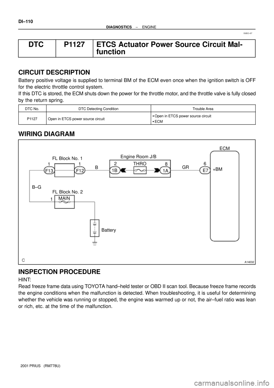
CIRCUIT DESCRIPTION
Battery positive voltage is supplied to terminal BM of the ECM even once when the ignition switch is OFF
for the electric throttle control system.
If this DTC is stored, the ECM shuts down the power for the throttle motor, and the throttle valve is fully closed
by the return spring.
DTC No.DTC Detecting ConditionTrouble Area
P1127Open in ETCS power source circuit�Open in ETCS power source circuit
�ECM
WIRING DIAGRAM
INSPECTION PROCEDURE
HINT:
Read freeze frame data using TOYOTA hand±held tester or OBD II scan tool. Because freeze frame records
the engine conditions when the malfunction is detected. When troubleshooting, it is useful for determining
whether the vehicle was running or stopped, the engine was warmed up or not, the air±fuel ratio was lean
or rich, etc. at the time of the malfunction.
DI2EC±07
Page 713 of 1943
A13630THRO FuseR/B No.2
A13631
BM
(+)(±)
± DIAGNOSTICSENGINE
DI±111
2001 PRIUS (RM778U)
1 Check THRO fuse of R/B No.2.
PREPARATION:
Remove the THRO fuse from the Engine room J/B.
CHECK:
Check the countinuity of the THRO fuse.
OK:
Continuity
NG Check for short in all harness and components
connected to THRO fuse.
OK
2 Check voltage between terminal +BM of ECM connector and body ground.
PREPARATION:
Remove the ECM with connector still connected (See page
SF±62).
CHECK:
Measure the voltage between terminal BM of the ECM connec-
tor and body ground.
OK:
Voltage: 9 ± 14 V
OK Check and replace ECM (See page IN±41).
NG
Check and repair harness or connector be-
tween battery and ETCS fuse, and ETCS fuse
and ECM (See page IN±41).
Page 717 of 1943

A14055
BatteryEAN1
Noise
Filter Engine Room J/B
Ignition SW Instrument
Panel J/B3
B±R I4 Ignition Coil
and Igniter No. 4
1ECM
14
Y
E7
E7
E7
E7 13
12
25IGT4
IGT3
IGT2
IGF
E711
IGT1 1
2
4
G
W
B±R
B±R
Y±G 3
4
2 1I3 Ignition Coil
and Igniter No. 3
3
4
2 1I2 Ignition Coil
and Igniter No. 2
2 I1 Ignition Coil
and Igniter No. 1
1
3
4
B±W
B±W
B±W
B±W
B±W
B±W
B±RB±RB±R
B±R
W±B W±B
W±B
W±B
W±B
W±B
B±W
W±B B±W
W±R
B±W IG2 Relay
5
1 3
29
1J
3
1J 2
1A
3
1K
AM2
2
1B
B
F12
12G 11
2B 5
2C 22G 1
B±W
W±R
67
IG2AM2
FL
Block
No. 1
F13
1
B±G
FL
Block
No. 2
MAIN
W±B
A
AJ7
J/C
W±B
A
J1
J/C
IE
B±W
DI±116
± DIAGNOSTICSENGINE
2001 PRIUS (RM778U)
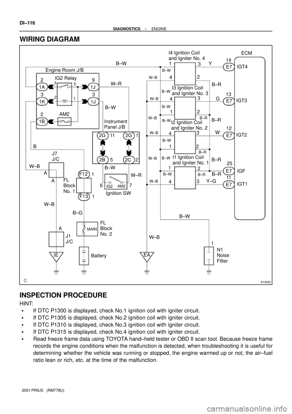
WIRING DIAGRAM
INSPECTION PROCEDURE
HINT:
�If DTC P1300 is displayed, check No.1 ignition coil with igniter circuit.
�If DTC P1305 is displayed, check No.2 ignition coil with igniter circuit.
�If DTC P1310 is displayed, check No.3 ignition coil with igniter circuit.
�If DTC P1315 is displayed, check No.4 ignition coil with igniter circuit.
�Read freeze frame data using TOYOTA hand±held tester or OBD II scan tool. Because freeze frame
records the engine conditions when the malfunction is detected, when troubleshooting it is useful for
determining whether the vehicle was running or stopped, the engine warmed up or not, the air±fuel
ratio lean or rich, etc. at the time of the malfunction.
Page 724 of 1943
A14061A14062A14465
OCV Connector
(a)
(b)
DI±124
± DIAGNOSTICSENGINE
2001 PRIUS (RM778U)
NG
Replace ECM.
OBD II scan tool (excluding TOYOTA hand±held tester)
1 Check valve timing (See page EM±21).
NG Repair valve timing.
OK
2 Check operation of OCV.
PREPARATION:
Start the engine.
CHECK:
(a) Check the engine speed when disconnect the OCV con-
nector.
(b) Check the engine speed when apply battery positive volt-
age between terminals of OCV.
RESULT:
ResultCheck (a)Check (b)
1Normal engine speedRough idle or engine stall
2Except 1
2 Go to step 4.
1
Page 742 of 1943
A14034
Battery
MAIN
FL Block No. 1
F131
B±GEngine Room J/B
1B43
E8BATT ECM
12
1A F12R±W EFI
FL Block No. 2B
1
± DIAGNOSTICSENGINE
DI±143
2001 PRIUS (RM778U)
DTC P1600 ECM BATT Malfunction
CIRCUIT DESCRIPTION
Battery positive voltage is supplied to terminal BATT of the ECM even when the ignition switch is OFF for
use by the DTC memory and air±fuel ratio adaptive control value memory, etc.
DTC No.DTC Detecting ConditionTrouble Area
P1600Open in back up power source circuit�Open in back up power source circuit
�ECM
HINT:
If DTC P1600 appear, the ECM does not store another DTC.
WIRING DIAGRAM
INSPECTION PROCEDURE
HINT:
Read freeze frame data using TOYOTA hand±held tester or OBD II scan tool. Because freeze frame records
the engine conditions when the malfunction is detected, when troubleshooting it is useful for determining
whether the vehicle was running or stopped, the engine warmed up or not, the air±fuel ratio lean or rich, etc.
at the time of the malfunction.
DI6VN±02
Page 743 of 1943
A13634
LOCK
BATT
(±)
(+)
A13630
Engine Room J/B
EFI Fuse
DI±144
± DIAGNOSTICSENGINE
2001 PRIUS (RM778U)
1 Check voltage between terminal BATT of ECM connector and body ground.
PREPARATION:
Remove the ECM with connector still connected (See page
SF±62).
CHECK:
Measure voltage between terminal BATT of the ECM connector
and body ground.
OK:
Voltage: 9 ± 14 V
OK Check and replace ECM (See page IN±41).
NG
2 Check EFI fuse.
PREPARATION:
Remove the EFI fuse from the engine room J/B.
CHECK:
Check continuity of EFI fuse.
OK:
Continuity
NG Check for short in all the harness and
components connected to EFI fuse.
OK
Check and repair harness or connector
between battery and EFI fuse and ECM
(See page IN±41).