Page 1019 of 1943

± DIAGNOSTICSANTI±LOCK BRAKE SYSTEM WITH EBD & RBS
DI±443
2001 PRIUS (RM778U)
INSPECTION PROCEDURE
HINT:
Troubleshoot in accordance with the chart below for each trouble symptom.
ABS warning light does not light up*1
ABS warning light remains on*2
*1: Start the inspection from step 1 in case of using the TOYOTA hand±held tester and start from step 2 in
case of not using TOYOTA hand±held tester.
*2: After inspection with step 4, start the inspection from step 5 in case of using the TOYOTA hand±held
tester and start from step 6 in case of not using TOYOTA hand±held tester.
1 Check operation of the brake warning light.
PREPARATION:
(a) Connect the TOYOTA hand±held tester to the DLC3.
(b) Turn the ignition switch ON, and push the TOYOTA hand±held tester main switch ON.
(c) Select the ACTIVE TEST mode on the TOYOTA hand±held tester.
CHECK:
Check that ºONº and ºOFFº of the ABS warning light can be shown on the combination meter on the TOYOTA
hand±held tester.
OK Check and replace brake ECU.
NG
2 Check ABS warning light.
See combination meter troubleshooting on page BE±2.
NG Repair bulb or combination meter assembly.
OK
Page 1020 of 1943

F00043
1 2 3
4 5 6
1 2 3
4 5 6
1 2 3
4
65 Open
Continuity
Continuity
Continuity
Open
(+)(±)
(+) (±)1 2 3
4 5 6 Continuity
DI±444
± DIAGNOSTICSANTI±LOCK BRAKE SYSTEM WITH EBD & RBS
2001 PRIUS (RM778U)
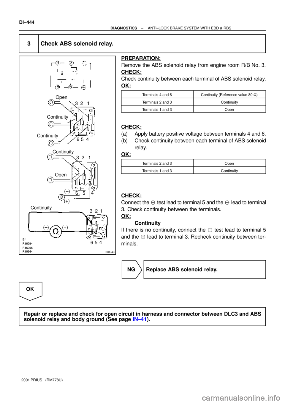
3 Check ABS solenoid relay.
PREPARATION:
Remove the ABS solenoid relay from engine room R/B No. 3.
CHECK:
Check continuity between each terminal of ABS solenoid relay.
OK:
Terminals 4 and 6Continuity (Reference value 80 W)
Terminals 2 and 3Continuity
Terminals 1 and 3Open
CHECK:
(a) Apply battery positive voltage between terminals 4 and 6.
(b) Check continuity between each terminal of ABS solenoid
relay.
OK:
Terminals 2 and 3Open
Terminals 1 and 3Continuity
CHECK:
Connect the � test lead to terminal 5 and the � lead to terminal
3. Check continuity between the terminals.
OK:
Continuity
If there is no continuity, connect the � test lead to terminal 5
and the � lead to terminal 3. Recheck continuity between ter-
minals.
NG Replace ABS solenoid relay.
OK
Repair or replace and check for open circuit in harness and connector between DLC3 and ABS
solenoid relay and body ground (See page IN±41).
Page 1021 of 1943
± DIAGNOSTICSANTI±LOCK BRAKE SYSTEM WITH EBD & RBS
DI±445
2001 PRIUS (RM778U)
4 Check that the brake ECU connectors are securely connected to the brake ECU.
NO Connect the connector to the brake ECU.
YES
5 Check operation of the ABS warning light (See step 1).
OK Check and replace brake ECU.
NG
6 Is DTC output?
Check DTC on page DI±353.
YES Repair circuit indicated by the output code.
NO
7 Check ABS solenoid relay (See step 3).
NG Replace ABS solenoid relay.
OK
Check for short circuit in harness and connector between DLC3 and ABS solenoid relay (See
page IN±41).
Page 1023 of 1943

± DIAGNOSTICSANTI±LOCK BRAKE SYSTEM WITH EBD & RBS
DI±447
2001 PRIUS (RM778U)
INSPECTION PROCEDURE
HINT:
Start the inspection from step 1 in case of using the TOYOTA hand±held tester and start from step 2 in case
of not using the TOYOTA hand±held tester.
1 Check operation of the BRAKE warning light.
PREPARATION:
(a) Release the parking brake pedal.
(b) Connect the TOYOTA hand±held tester to the DLC3.
(c) Turn the ignition switch ON, and push the TOYOTA hand±held tester main switch ON.
(d) Select the ACTIVE TEST mode on the TOYOTA hand±held tester.
CHECK:
Check that ºONº and ºOFFº of BRAKE warning light can be shown on the combination meter by the TOYOTA
hand±held tester.
OK Check and replace brake ECU.
NG
2 Check parking brake switch circuit (See page BE±2).
NG Repair or replace parking brake switch circuit.
OK
3 Check brake fluid level warning switch circuit (See page BE±2).
NG Repair or replace brake fluid level warning
switch circuit.
OK
4 Is DTC output for ABS ?
Yes Repair circuit indicated by the output code.
No
Page 1028 of 1943
F12686
DLC3
2DTc 3
Tc
8
4 CG13ID1 P±B P±B
B11
W±B
AJ11
J/C
A
ID C
Instrument Panel J/BBrake ECU
J16
J/C J26
J/C
J24
J/CP±B P±B
E E
C
W±B W±B
A2K 82
F09678
CG TcDLC3 ON
(+) (±)
DI±452
± DIAGNOSTICSANTI±LOCK BRAKE SYSTEM WITH EBD & RBS
2001 PRIUS (RM778U)
Tc Terminal Circuit
CIRCUIT DESCRIPTION
Connecting terminals Tc and CG of the DLC3 causes the ECU to display the DTC by flashing the ABS warn-
ing light.
WIRING DIAGRAM
INSPECTION PROCEDURE
1 Check voltage between terminals Tc and CG of DLC3.
PREPARATION:
Turn the ignition switch ON.
CHECK:
Measure voltage between terminal Tc and CG of DLC3.
OK:
Voltage: 10 ± 14 V
OK If ABS warning light does not blink even after Tc
and CG are connected, the ECU may be defec-
tive.
NG
DI29I±13
Page 1031 of 1943
F09679
ON
DLC3 (+) (±)
Ts
CG
± DIAGNOSTICSANTI±LOCK BRAKE SYSTEM WITH EBD & RBS
DI±455
2001 PRIUS (RM778U)
INSPECTION PROCEDURE
1 Check voltage between terminals Ts and CG of DLC3.
CHECK:
(a) Turn the ignition switch ON.
(b) Measure voltage between terminals Ts and CG of DLC3.
OK:
Voltage: 10 ± 14 V
OK If ABS warning light does not blink even after Ts
and CG are connected, the ECU may be defec-
tive.
NG
2 Check for open and short circuit in harness and connector between brake ECU
and DLC3, DLC3 and body ground (See page IN±41).
NG Repair or replace harness or connector.
OK
Check and replace brake ECU.
Page 1048 of 1943
F12822
ON
WRRWRL
PGND
PGND
DI±480
± DIAGNOSTICSELECTRIC MOTOR POWER STEERING
2001 PRIUS (RM778U)
INSPECTION PROCEDURE
1 Check continuity between terminals WRR and PGND, WRL and PGND of EMPS
ECU connector.
PREPARATION:
Remove the EMPS ECU with connectors still connected.
CHECK:
Turn the ignition switch ON and measure the resistance be-
tween terminals WRR and PGND, WRL and PGND of EMPS
ECU connector.
OK:
Resistance:1M W or higher
NG Check and replace the EMPS ECU.
OK
2 Check for open and short circuit in harness and connector between terminals
WRR of EMPS ECU connector and RRO of brake ECU connector, WRL of EMPS
ECU and RLO of brake ECU connector (See page IN±41).
NG Repair and replace harness or connector.
OK
3 Check the DTC for the ABS with EBD and RBS (See page DI±351).
*1 Repair ABS with EBD and RBS control system
according to the code output.
*1: Output NG code
Page 1220 of 1943

DI7XR±01
I17803
Connector ºAº Connector ºBº
(LHD model) COMBINATION METER DI±672
± DIAGNOSTICSCOMBINATION METER SYSTEM
2001 PRIUS (RM778U)
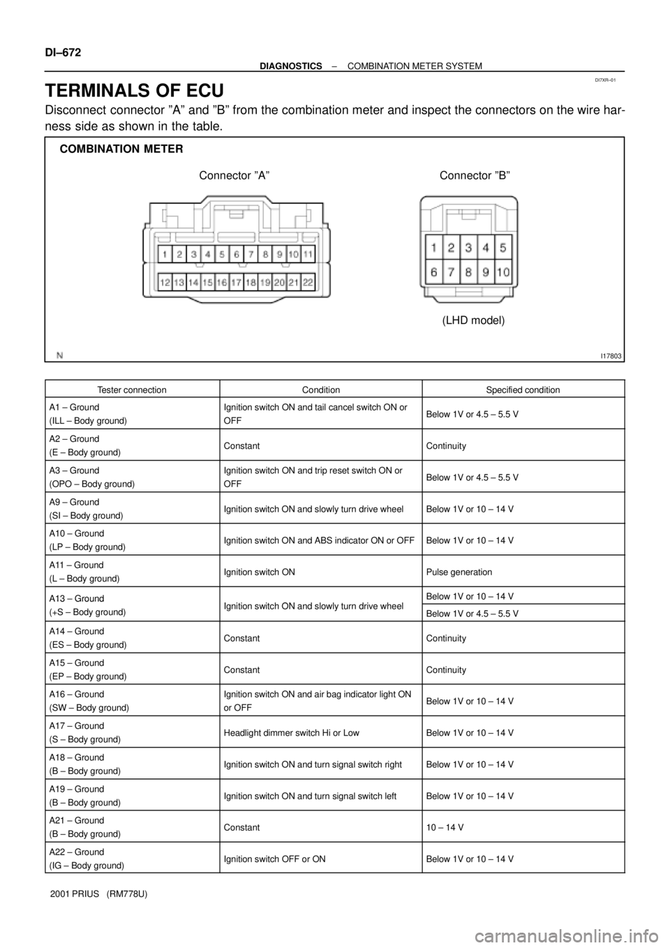
TERMINALS OF ECU
Disconnect connector ºAº and ºBº from the combination meter and inspect the connectors on the wire har-
ness side as shown in the table.
Tester connectionConditionSpecified condition
A1 ± Ground
(ILL ± Body ground)Ignition switch ON and tail cancel switch ON or
OFFBelow 1V or 4.5 ± 5.5 V
A2 ± Ground
(E ± Body ground)ConstantContinuity
A3 ± Ground
(OPO ± Body ground)Ignition switch ON and trip reset switch ON or
OFFBelow 1V or 4.5 ± 5.5 V
A9 ± Ground
(SI ± Body ground)Ignition switch ON and slowly turn drive wheelBelow 1V or 10 ± 14 V
A10 ± Ground
(LP ± Body ground)Ignition switch ON and ABS indicator ON or OFFBelow 1V or 10 ± 14 V
A11 ± Ground
(L ± Body ground)Ignition switch ONPulse generation
A13 ± GroundI iti it h ON d l l t d i h lBelow 1V or 10 ± 14 VA13 Ground
(+S ± Body ground)Ignition switch ON and slowly turn drive wheelBelow 1V or 4.5 ± 5.5 V
A14 ± Ground
(ES ± Body ground)ConstantContinuity
A15 ± Ground
(EP ± Body ground)ConstantContinuity
A16 ± Ground
(SW ± Body ground)Ignition switch ON and air bag indicator light ON
or OFFBelow 1V or 10 ± 14 V
A17 ± Ground
(S ± Body ground)Headlight dimmer switch Hi or LowBelow 1V or 10 ± 14 V
A18 ± Ground
(B ± Body ground)Ignition switch ON and turn signal switch rightBelow 1V or 10 ± 14 V
A19 ± Ground
(B ± Body ground)Ignition switch ON and turn signal switch leftBelow 1V or 10 ± 14 V
A21 ± Ground
(B ± Body ground)Constant10 ± 14 V
A22 ± Ground
(IG ± Body ground)Ignition switch OFF or ONBelow 1V or 10 ± 14 V