Page 1670 of 1943
F11584
MP Grease No.2
SA±30
± SUSPENSION AND AXLEFRONT SHOCK ABSORBER
2001 PRIUS (RM778U)
(h) Apply MP grease No.2 into the suspension support.
CAUTION:
Do not touch grease on rubber surface of upper support.
(i) Install the cap.
Page 1671 of 1943

SA1ZW±01
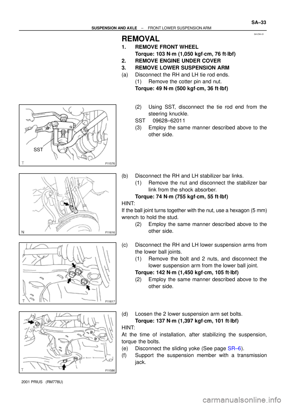
F11576
SST
F11616
F11617
F11586
± SUSPENSION AND AXLEFRONT LOWER SUSPENSION ARM
SA±33
2001 PRIUS (RM778U)
REMOVAL
1. REMOVE FRONT WHEEL
Torque: 103 N´m (1,050 kgf´cm, 76 ft´lbf)
2. REMOVE ENGINE UNDER COVER
3. REMOVE LOWER SUSPENSION ARM
(a) Disconnect the RH and LH tie rod ends.
(1) Remove the cotter pin and nut.
Torque: 49 N´m (500 kgf´cm, 36 ft´lbf)
(2) Using SST, disconnect the tie rod end from the
steering knuckle.
SST 09628±62011
(3) Employ the same manner described above to the
other side.
(b) Disconnect the RH and LH stabilizer bar links.
(1) Remove the nut and disconnect the stabilizer bar
link from the shock absorber.
Torque: 74 N´m (755 kgf´cm, 55 ft´lbf)
HINT:
If the ball joint turns together with the nut, use a hexagon (5 mm)
wrench to hold the stud.
(2) Employ the same manner described above to the
other side.
(c) Disconnect the RH and LH lower suspension arms from
the lower ball joints.
(1) Remove the bolt and 2 nuts, and disconnect the
lower suspension arm from the lower ball joint.
Torque: 142 N´m (1,450 kgf´cm, 105 ft´lbf)
(2) Employ the same manner described above to the
other side.
(d) Loosen the 2 lower suspension arm set bolts.
Torque: 137 N´m (1,397 kgf´cm, 101 ft´lbf)
HINT:
At the time of installation, after stabilizing the suspension,
torque the bolts.
(e) Disconnect the sliding yoke (See page SR±6).
(f) Support the suspension member with a transmission
jack.
Page 1673 of 1943
SA1ZU±01
F11598
SST
F11599
F11593
Wood
F11618
± SUSPENSION AND AXLEREAR SHOCK ABSORBER
SA±51
2001 PRIUS (RM778U)
REMOVAL
1. REMOVE REAR WHEELS
Torque: 103 N´m (250 kgf´cm, 18 ft´lbf)
2. REMOVE REAR SEAT (See page BO±83)
3. DISCONNECT BRAKE LINES
(a) Using SST, disconnect the brake lines from the flexible
hose. Use a container to catch brake fluid as it drains out.
SST 09751±36011
(b) Remove the clip.
(c) Employ the same manner described above to the other
side.
4. DISCONNECT ABS SPEED SENSOR WIRE HARNESS
Remove the 4 nuts, and disconnect the ABS speed sensor wire
harness from the axle beam.
Torque: 5.4 N´m (55 kgf´cm, 48 in.´lbf)
5. SUPPORT REAR AXLE BEAM AT RIGHT AND LEFT
SIDES WITH JACKS
6. REMOVE SHOCK ABSORBER
(a) Remove the 2 nuts and bolt.
Torque: 80 N´m (816 kgf´cm, 59 ft´lbf)
Page 1674 of 1943
F11619
SA±52
± SUSPENSION AND AXLEREAR SHOCK ABSORBER
2001 PRIUS (RM778U)
(b) Remove the nut, washer and shock absorber.
Torque: 80 N´m (816 kgf´cm, 59 ft´lbf)
Page 1678 of 1943

± BRAKETROUBLESHOOTING
BR±3
1518 Author�: Date�:
2001 PRIUS (RM778U) Noise from brakes
1. Pad or lining (Cracked or distorted)
2. Installation bolt (Loose)
3. Disc or drum (Scored)
4. Pad support plate (Loose)
5. Sliding pin (Worn)
6. Pad or lining (Dirty)
7. Pad or lining (Glazed)
8. Tension or return spring (Faulty)
9. Anti±squeal shim (Damaged)
10.Shoe hold±down spring (Damaged)BR±23
BR±32
BR±26
BR±26
BR±32
BR±23
BR±26
BR±23
BR±32
BR±23
BR±32
BR±32
BR±23
BR±32
Brake warning light lights up*1
(Parking brake pedal released)
1. Brake fluid level
2. Hydraulic brake booster power supply system (Faulty)
BR±41
Brake warning light lights up and brake warning buzzer sounds*2Hydraulic brake booster power supply system (Faulty)BR±41
ABS warning light lights up*31. Anti±lock brake system (Faulty)
2. Hydraulic brake booster power supply system (Faulty)
BR±41
*1, *3: The light may stay on for about 60 seconds after the engine has been started. It is normal if it goes
out after a while.
*
2, *3: Depressing the brake pedal repeatedly may turn on the warning light and buzzer. It is normal if the
light goes out and the buzzer stops sounding after a few seconds.
Page 1699 of 1943
F12238
Transponder Key Coil
Column Upper BracketKey Cylinder
Column Upper Clamp Key Unlock
Warning Switch
Tapered±head Bolt Ignition Switch Break Away Capsule
Energy Absorbing
Plate
Energy Absorbing
Plate Guide Energy Absorbing
Clip
Tilt Lever Lock BoltBreak Away Bracket
Snap Ring
Column Tube
Sub±assembly
Tilt Lever
No. 1 Tilt Steering
Support Reinforce Tilt Steering
Adjust Nut
Torsion Spring Steering Pawl Set Bolt No. 1 Tilt Steering
Support Collar Tilt Steering Support
Washer
Main Shaft Assembly
��
�
Energy Absorbing
Plate
�
Snap Ring
�
Tilt Sub Lever
Main Shaft Bushing
13 (130, 9)
9.5 (100, 87 in.´lbf)
5.4 (55, 48 in.´lbf)
N´m (kgf´cm, ft´lbf): Specified torque
Non±reusable part �Key Interlock Solenoid
No. 2
Tilt Lever
Lock Bolt
Molybdenum disulfide lithium base grease
± STEERINGTILT STEERING COLUMN
SR±5
1578 Author�: Date�:
2001 PRIUS (RM778U)
Page 1703 of 1943
SR1BG±01
F12223Screw Extractor
F12235
F12225
± STEERINGTILT STEERING COLUMN
SR±9
2001 PRIUS (RM778U)
DISASSEMBLY
NOTICE:
When using a vise, do not overtighten it.
1. REMOVE TRANSPONDER KEY COIL
Remove the screw and transponder key coil.
2. REMOVE COLUMN UPPER BRACKET AND COLUMN
UPPER CLAMP
(a) Using a centering punch, mark the center of the 2 ta-
pered±head bolts.
(b) Using a 3 ± 4 mm (0.12 ± 0.16 in.) drill, drill into the 2 bolts.
(c) Using a screw extractor, remove the 2 bolts, column up-
per bracket and column upper clamp.
3. REMOVE TILT STEERING SUPPORT
(a) Remove the look nut.
(b) Remove the washer, steering pawl set bolt and tilt steer-
ing support.
(c) Remove the 2 No. 1 tilt steering support collars.
4. REMOVE 2 ENERGY ABSORBING PLATES
(a) Using pliers, remove the 2 energy absorbing clips.
(b) Remove the 2 energy absorbing plates, 2 energy absorb-
ing guides, and 2 break away capsules.
5. REMOVE TORSION SPRING
Using a screw driver, remove the torsion spring.
Page 1706 of 1943

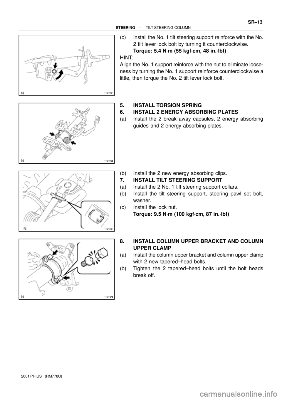
F12233
F12234
F12236
F12224
± STEERINGTILT STEERING COLUMN
SR±13
2001 PRIUS (RM778U)
(c) Install the No. 1 tilt steering support reinforce with the No.
2 tilt lever lock bolt by turning it counterclockwise.
Torque: 5.4 N´m (55 kgf´cm, 48 in.´lbf)
HINT:
Align the No. 1 support reinforce with the nut to eliminate loose-
ness by turning the No. 1 support reinforce counterclockwise a
little, then torque the No. 2 tilt lever lock bolt.
5. INSTALL TORSION SPRING
6. INSTALL 2 ENERGY ABSORBING PLATES
(a) Install the 2 break away capsules, 2 energy absorbing
guides and 2 energy absorbing plates.
(b) Install the 2 new energy absorbing clips.
7. INSTALL TILT STEERING SUPPORT
(a) Install the 2 No. 1 tilt steering support collars.
(b) Install the tilt steering support, steering pawl set bolt,
washer.
(c) Install the lock nut.
Torque: 9.5 N´m (100 kgf´cm, 87 in.´lbf)
8. INSTALL COLUMN UPPER BRACKET AND COLUMN
UPPER CLAMP
(a) Install the column upper bracket and column upper clamp
with 2 new tapered±head bolts.
(b) Tighten the 2 tapered±head bolts until the bolt heads
break off.