Page 1764 of 1943

± BODY ELECTRICALTROUBLESHOOTING
BE±7
1674 Author�: Date�:
2001 PRIUS (RM778U)
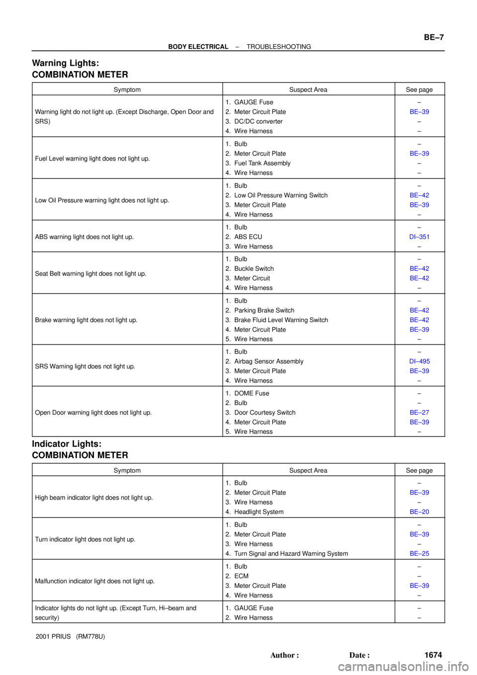
Warning Lights:
COMBINATION METER
SymptomSuspect AreaSee page
Warning light do not light up. (Except Discharge, Open Door and
SRS)
1. GAUGE Fuse
2. Meter Circuit Plate
3. DC/DC converter
4. Wire Harness±
BE±39
±
±
Fuel Level warning light does not light up.
1. Bulb
2. Meter Circuit Plate
3. Fuel Tank Assembly
4. Wire Harness±
BE±39
±
±
Low Oil Pressure warning light does not light up.
1. Bulb
2. Low Oil Pressure Warning Switch
3. Meter Circuit Plate
4. Wire Harness±
BE±42
BE±39
±
ABS warning light does not light up.
1. Bulb
2. ABS ECU
3. Wire Harness±
DI±351
±
Seat Belt warning light does not light up.
1. Bulb
2. Buckle Switch
3. Meter Circuit
4. Wire Harness±
BE±42
BE±42
±
Brake warning light does not light up.
1. Bulb
2. Parking Brake Switch
3. Brake Fluid Level Warning Switch
4. Meter Circuit Plate
5. Wire Harness±
BE±42
BE±42
BE±39
±
SRS Warning light does not light up.
1. Bulb
2. Airbag Sensor Assembly
3. Meter Circuit Plate
4. Wire Harness±
DI±495
BE±39
±
Open Door warning light does not light up.
1. DOME Fuse
2. Bulb
3. Door Courtesy Switch
4. Meter Circuit Plate
5. Wire Harness±
±
BE±27
BE±39
±
Indicator Lights:
COMBINATION METER
SymptomSuspect AreaSee page
High beam indicator light does not light up.
1. Bulb
2. Meter Circuit Plate
3. Wire Harness
4. Headlight System±
BE±39
±
BE±20
Turn indicator light does not light up.
1. Bulb
2. Meter Circuit Plate
3. Wire Harness
4. Turn Signal and Hazard Warning System±
BE±39
±
BE±25
Malfunction indicator light does not light up.
1. Bulb
2. ECM
3. Meter Circuit Plate
4. Wire Harness±
±
BE±39
±
Indicator lights do not light up. (Except Turn, Hi±beam and
security)1. GAUGE Fuse
2. Wire Harness±
±
Page 1770 of 1943
I17787
Engine room J/B:
Fuses:
1. HTR Fuse
2. RDI Fuse
3. ABS No. 2 Fuse
4. CDS FAN Fuse
5. HORN Fuse
6. THRO Fuse
7. ABS No. 3 Fuse
8. TURN±HAZ Fuse
9. AM2 Fuse
10. BATT FANRelays:
A. FAN NO. 1 Relay
B. FAN NO. 2 Relay
C. FAN NO. 3 Relay
D. IG2 Relay
E. HORN Relay
F. HTR Relay
G. EFI Relay
H. CLR MG Relay
I. HEAD Relay
J. CIR OPN Relay
K. DIM Relay *1
123 4 5 6 7 8
91011
121314
1516
17
18 K
J
A B
C D E
F
G H
I
11. DOME Fuse
12. HEAD HI (RH) Fuse *1
13. HEAD HI (LH) Fuse *1
14. HEAD LO (LH) *1
HEAD (LH) *2
15. HEAD LO (RH) *1
HEAD (RH) *2
16. EFI Fuse
17. HEV Fuse
18. HEAD Fuse *1
*1: w/ Daytime Running Light
*2: w/o Daytime Running Light
± BODY ELECTRICALPOWER SOURCE
BE±13
1680 Author�: Date�:
2001 PRIUS (RM778U)
Page 1772 of 1943
I17789
1 2 3456
7 A B
C
D E
Fuses: Relays: Engine Room R/B No. 3:
G H
1. HTR2 Fuse
2. HTR1 Fuse
3. ABS No. 4 Fuse
4. ABS No. 1 Fuse5. EMPS Fuse
6. HTR3 Fuse
7. DRL FuseA. A/C W/P Relay
B. ABS SOL Relay
C. DRL Relay
D. HTR2 RelayE. HTR1 Relay
G. HTR3 Relay
H. EPMS Relay
Engine Room R/B No. 2:
A B C
Relays:
A. IGCT Relay
B. HYDRO MTR No. 2 Relay
C. HYDRO MTR No. 1 Relay
± BODY ELECTRICALPOWER SOURCE
BE±15
1682 Author�: Date�:
2001 PRIUS (RM778U)
Page 1785 of 1943
I17798
A20
A12
A14
A2
A3
A1
B7
B6
B1
A9
A11
A13
A22
A21
B2
B3Conversion
Drive unit
Correspon
dence
Buzzer
Power Supply
Circuit (VFD)
ECU
Drive unit
Open door indicator
Illumination
Brake warning
Driver seat belt warning
Low oil pressure warning
Discharge warning
CRUISE main indicator
Engine coolant warning (Low)
Engine coolant warning (High)
Passenger seat belt warning
Malfunction indicator
ABS warning
SRS warning
Left turn indicator
Right turn indicator
Hi±beam indicator B5
A19
A18
A17A15 A16 A10 B4 Output control indicator BE±40
± BODY ELECTRICALCOMBINATION METER
2001 PRIUS (RM778U)
Page 1786 of 1943
No. Wiring connector side
1
2
3
10
11
12
13
14
15
16
17
18
19
20
21
22EMPS ECU
Fuel tank temperature (+)
Hybrid vehicle control ECU (4P)
Ground
Ground
Center airbag sensor assembly
Headlight dimmer switch
Turn signal switch (Right)
Turn signal switch (Left)
Fuel tank temperature (±)
DOME Fuse
GAUGE FuseODO/TRIP switch (TC)
ODO/TRIP switch (E)
ODO/TRIP switch (ODO)
9 ABS ECU (SI)
ABS ECU (ABS)
2
3
4
5
6
7 1 Back±up light relay
Body ECU
Engine ECM
ACC Fuse
Light control rheostat (TC)
Light control rheostat (TR) A
BBody ECU
± BODY ELECTRICALCOMBINATION METER
BE±41
2001 PRIUS (RM778U)
Page 1787 of 1943

BE1VU±02
I17803
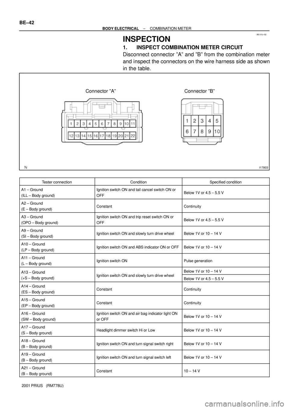
Connector ºAº Connector ºBº BE±42
± BODY ELECTRICALCOMBINATION METER
2001 PRIUS (RM778U)
INSPECTION
1. INSPECT COMBINATION METER CIRCUIT
Disconnect connector ºAº and ºBº from the combination meter
and inspect the connectors on the wire harness side as shown
in the table.
Tester connectionConditionSpecified condition
A1 ± Ground
(ILL ± Body ground)Ignition switch ON and tail cancel switch ON or
OFFBelow 1V or 4.5 ± 5.5 V
A2 ± Ground
(E ± Body ground)ConstantContinuity
A3 ± Ground
(OPO ± Body ground)Ignition switch ON and trip reset switch ON or
OFFBelow 1V or 4.5 ± 5.5 V
A9 ± Ground
(SI ± Body ground)Ignition switch ON and slowly turn drive wheelBelow 1V or 10 ± 14 V
A10 ± Ground
(LP ± Body ground)Ignition switch ON and ABS indicator ON or OFFBelow 1V or 10 ± 14 V
A11 ± Ground
(L ± Body ground)Ignition switch ONPulse generation
A13 ± GroundI iti it h ON d l l t d i h lBelow 1V or 10 ± 14 VA13 Ground
(+S ± Body ground)Ignition switch ON and slowly turn drive wheelBelow 1V or 4.5 ± 5.5 V
A14 ± Ground
(ES ± Body ground)ConstantContinuity
A15 ± Ground
(EP ± Body ground)ConstantContinuity
A16 ± Ground
(SW ± Body ground)Ignition switch ON and air bag indicator light ON
or OFFBelow 1V or 10 ± 14 V
A17 ± Ground
(S ± Body ground)Headlight dimmer switch Hi or LowBelow 1V or 10 ± 14 V
A18 ± Ground
(B ± Body ground)Ignition switch ON and turn signal switch rightBelow 1V or 10 ± 14 V
A19 ± Ground
(B ± Body ground)Ignition switch ON and turn signal switch leftBelow 1V or 10 ± 14 V
A21 ± Ground
(B ± Body ground)Constant10 ± 14 V
Page 1864 of 1943

BO3PT±01
H15398
Matchmarks
H15396
± BODYFRONT WIPER AND WASHER
BO±35
2001 PRIUS (RM778U)
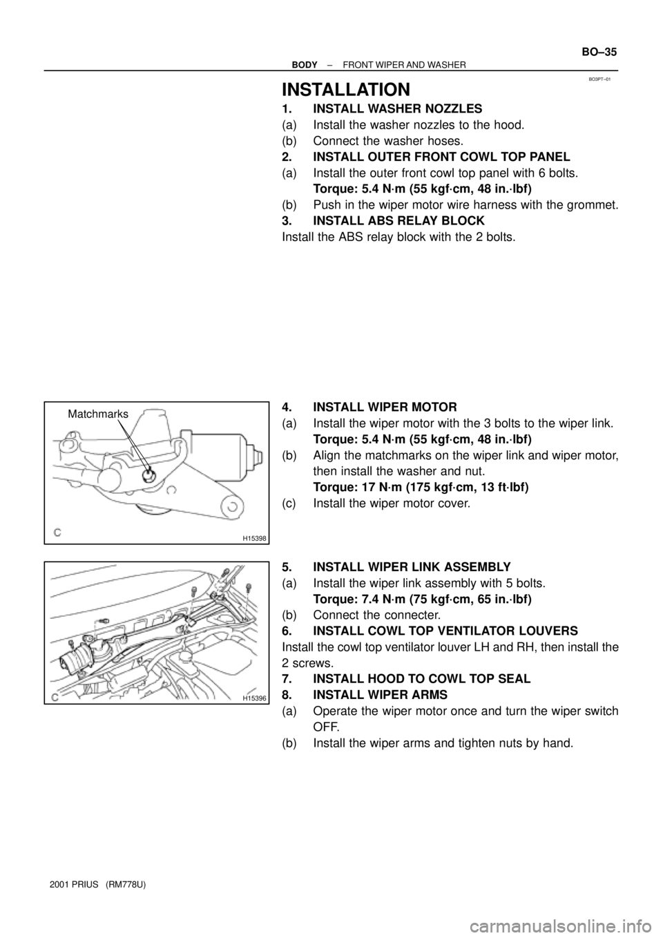
INSTALLATION
1. INSTALL WASHER NOZZLES
(a) Install the washer nozzles to the hood.
(b) Connect the washer hoses.
2. INSTALL OUTER FRONT COWL TOP PANEL
(a) Install the outer front cowl top panel with 6 bolts.
Torque: 5.4 N´m (55 kgf´cm, 48 in.´lbf)
(b) Push in the wiper motor wire harness with the grommet.
3. INSTALL ABS RELAY BLOCK
Install the ABS relay block with the 2 bolts.
4. INSTALL WIPER MOTOR
(a) Install the wiper motor with the 3 bolts to the wiper link.
Torque: 5.4 N´m (55 kgf´cm, 48 in.´lbf)
(b) Align the matchmarks on the wiper link and wiper motor,
then install the washer and nut.
Torque: 17 N´m (175 kgf´cm, 13 ft´lbf)
(c) Install the wiper motor cover.
5. INSTALL WIPER LINK ASSEMBLY
(a) Install the wiper link assembly with 5 bolts.
Torque: 7.4 N´m (75 kgf´cm, 65 in.´lbf)
(b) Connect the connecter.
6. INSTALL COWL TOP VENTILATOR LOUVERS
Install the cowl top ventilator louver LH and RH, then install the
2 screws.
7. INSTALL HOOD TO COWL TOP SEAL
8. INSTALL WIPER ARMS
(a) Operate the wiper motor once and turn the wiper switch
OFF.
(b) Install the wiper arms and tighten nuts by hand.