Page 959 of 1943

F12672
Brake ECU
AST Engine Room R/B No. 3
ABS Solenoid
Relay 3 W
DC/DCW±R
Y±B
R1+
SR 14
W±BBrake Actuator FL
Block
No. 11
1
1ABS No. 1
F10
MAIN
BatteryA
A B±G
J7
J/CB±L
BS7
21
1
B±O 3
Engine Room
R/B No. 3
FL
Block
No. 2F13
A
IEJ1
J/C W±B
B10
B13 B11 B1
Brake
ECU 3
3 3
3 33
64
B2
B3 AST6 6
Y±B
19 2 1
R
± DIAGNOSTICSANTI±LOCK BRAKE SYSTEM WITH EBD & RBS
DI±381
2001 PRIUS (RM778U)
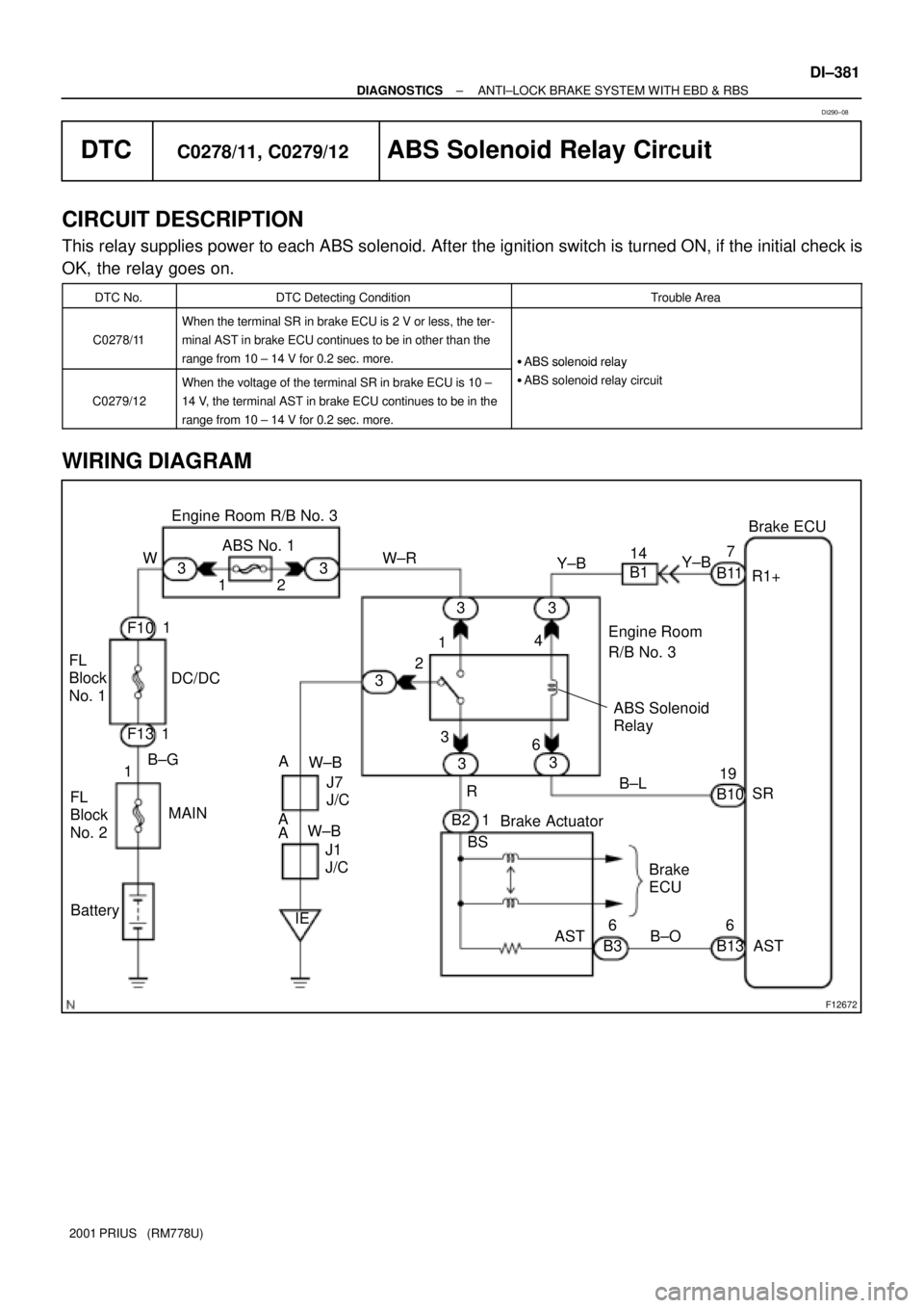
DTCC0278/11, C0279/12ABS Solenoid Relay Circuit
CIRCUIT DESCRIPTION
This relay supplies power to each ABS solenoid. After the ignition switch is turned ON, if the initial check is
OK, the relay goes on.
DTC No.DTC Detecting ConditionTrouble Area
C0278/11
When the terminal SR in brake ECU is 2 V or less, the ter-
minal AST in brake ECU continues to be in other than the
range from 10 ± 14 V for 0.2 sec. more.
�ABS solenoid relay
C0279/12
When the voltage of the terminal SR in brake ECU is 10 ±
14 V, the terminal AST in brake ECU continues to be in the
range from 10 ± 14 V for 0.2 sec. more.
�ABS solenoid relay
�ABS solenoid relay circuit
WIRING DIAGRAM
DI290±08
Page 960 of 1943

F12662
LOCK
1 2
Engine Room R/B No. 3
DI±382
± DIAGNOSTICSANTI±LOCK BRAKE SYSTEM WITH EBD & RBS
2001 PRIUS (RM778U)
INSPECTION PROCEDURE
HINT:
Start the inspection from step 1 in case of using the TOYOTA hand±held tester and start from step 2 in case
of not using the TOYOTA hand±held tester.
1 Check ABS solenoid relay operation.
PREPARATION:
(a) Connect the TOYOTA hand±held tester to the DLC3.
(b) Turn the ignition switch ON, and push the TOYOTA hand±held tester main switch ON.
(c) Select the ACTIVE TEST mode on the TOYOTA hand±held tester.
CHECK:
Check the operation sound of the ABS solenoid relay when operating it with the TOYOTA hand±held tester.
OK:
The operation sound of the ABS solenoid relay should be heard.
OK Go to step 4.
NG
2 Check voltage between terminals 1 and 2 of engine room R/B No. 3 (for ABS so-
lenoid relay).
PREPARATION:
Remove the ABS solenoid relay from engine room R/B No. 3.
CHECK:
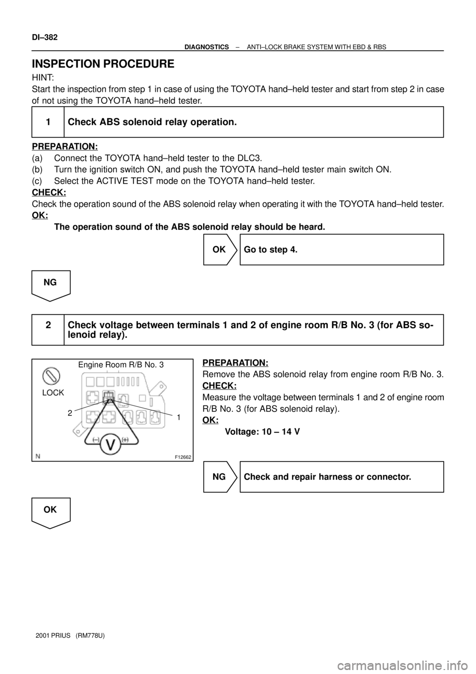
Measure the voltage between terminals 1 and 2 of engine room
R/B No. 3 (for ABS solenoid relay).
OK:
Voltage: 10 ± 14 V
NG Check and repair harness or connector.
OK
Page 961 of 1943
F00042
1 34
6 Open
(+)(±)1 2 3
4
4 5 6
1 2
3
2 5 6
5 Continuity
ContinuityContinuity
Open
± DIAGNOSTICSANTI±LOCK BRAKE SYSTEM WITH EBD & RBS
DI±383
2001 PRIUS (RM778U)
3 Check ABS solenoid relay.
CHECK:
Check continuity between each terminal of ABS solenoid relay.
OK:
Terminals 4 and 6Continuity
(Reference value 80 W)
Terminals 2 and 3Continuity
Terminals 1 and 3Open
CHECK:
(a) Apply battery positive voltage between terminals 4 and 6.
(b) Check continuity between each terminal of ABS solenoid
relay.
OK:
Terminals 2 and 3Open
Terminals 1 and 3Continuity
NG Replace ABS solenoid relay.
OK
Page 962 of 1943
F12443
ABS Solenoid
RelayEngine Room R/B
No. 3
Brake
Actuator
Brake ECU
ASTBS3
ASTAST
DI±384
± DIAGNOSTICSANTI±LOCK BRAKE SYSTEM WITH EBD & RBS
2001 PRIUS (RM778U)
4 Check continuity between terminals 3 of engine room R/B No. 3 (for ABS sole-
noid relay) and terminal AST of brake ECU.
CHECK:
Check continuity between terminal 3 of engine room R/B No. 3
(for ABS solenoid relay) and terminal AST of brake ECU.
OK:
Continuity
HINT:
There is a resistance of approx. 33 W between terminals BS and
AST of the brake actuator.
NG Repair or replace harness or brake actuator.
OK
5 Check for open and short circuit in harness and connector between ABS sole-
noid relay and brake ECU (See page IN±41).
NG Repair or replace harness or connector.
OK
If the same code is still output after the DTC is deleted, check the contact condition of each con-
nection. If the connections are normal, the ECU may be defective.
Page 967 of 1943
F12675
V
22 1424
16
R
W±B LG
AHVI± Brake ECU
HV ECU
J11
J/C
IDA(Shielded)
B11 B11 B11 B11 HVI+
HVO+
HVO± HTB+
HTB±
BTH± BTH+H14
H14
H14
H14G (Shielded)
W±B
A AJ10
J/C W±B 20
30
18
17
± DIAGNOSTICSANTI±LOCK BRAKE SYSTEM WITH EBD & RBS
DI±389
2001 PRIUS (RM778U)
DTC C1213/63 HV ECU Communication Circuit
Malfunction
CIRCUIT DESCRIPTION
The circuit is used to send RBS control information from the brake ECU to the HV ECU (HVI+, HVI±), and
HV control information from the HV ECU to the ABS ECU (HVO+, HVO±).
DTC No.DTC Detecting ConditionTrouble Area
C1213/63When the ignition switch is ON, abnormal communication
with HV ECU continues for 0.5 sec. or more.�HVI+ or HVI± circuit
�HVO+ or HVO± circuit
�HV ECU
WIRING DIAGRAM
DI1H0±10
Page 969 of 1943

F12676
B±G
F101
3 Engine Room R/B No. 3
DC/DC FL Block No. 1
7Brake ECU
L W22
+BS
B13
8 ABS No. 4
1
F13
Battery2
B3 1
8 1
7 B3
B3
B3B13
B13
B13 B13
LG
P
V1
16 L
3
1
2
FL
Block
No. 2
Brake ActuatorSLA+
SLA±
SLR+
SLR± MAIN DI±392
± DIAGNOSTICSANTI±LOCK BRAKE SYSTEM WITH EBD & RBS
2001 PRIUS (RM778U)
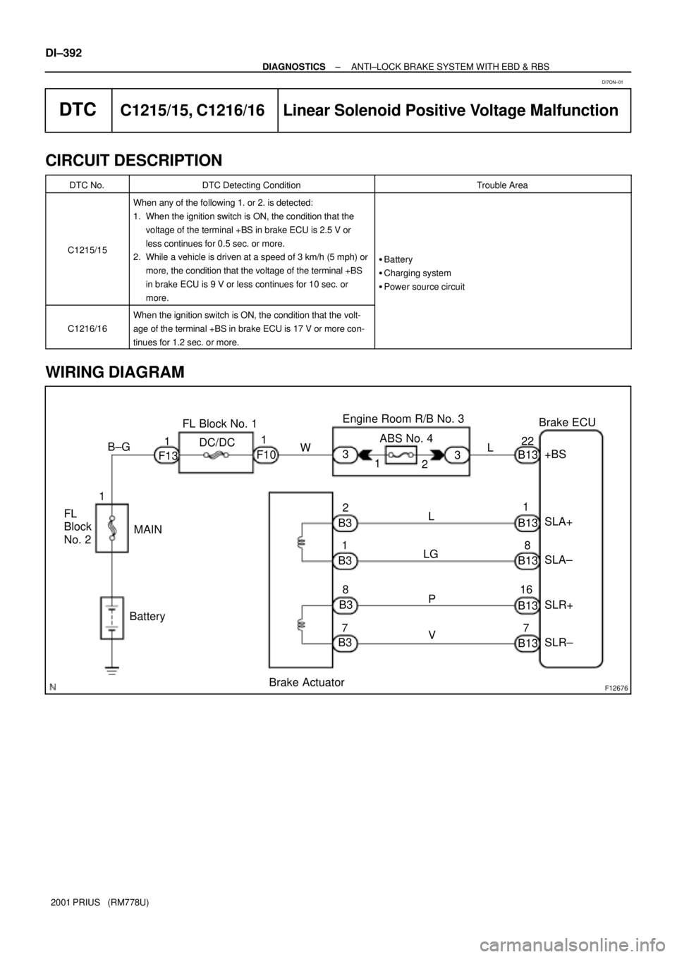
DTCC1215/15, C1216/16 Linear Solenoid Positive Voltage Malfunction
CIRCUIT DESCRIPTION
DTC No.DTC Detecting ConditionTrouble Area
C1215/15
When any of the following 1. or 2. is detected:
1. When the ignition switch is ON, the condition that the
voltage of the terminal +BS in brake ECU is 2.5 V or
less continues for 0.5 sec. or more.
2. While a vehicle is driven at a speed of 3 km/h (5 mph) or
more, the condition that the voltage of the terminal +BS
in brake ECU is 9 V or less continues for 10 sec. or
more.
�Battery
�Charging system
�Power source circuit
C1216/16
When the ignition switch is ON, the condition that the volt-
age of the terminal +BS in brake ECU is 17 V or more con-
tinues for 1.2 sec. or more.
WIRING DIAGRAM
DI7ON±01
Page 970 of 1943
F12445
Engine Room R/B No. 3
ABS No. 4
± DIAGNOSTICSANTI±LOCK BRAKE SYSTEM WITH EBD & RBS
DI±393
2001 PRIUS (RM778U)
INSPECTION PROCEDURE
1 Check ABS No. 4 fuse.
PREPARATION:
Remove the ABS No. 4 fuse from engine room R/B No. 3.
CHECK:
Check continuity of ABS No. 4 fuse.
OK:
Continuity
NG Check for short circuit in all the harness and
components connected to ABS No. 4 fuse (See
attached wiring diagram).
OK
2 Check battery positive voltage.
OK:
Voltage: 10 ± 14 V
NG Check and repair the charging system (See
page HV±39).
OK
Page 971 of 1943
F10937
GND+BS
DI±394
± DIAGNOSTICSANTI±LOCK BRAKE SYSTEM WITH EBD & RBS
2001 PRIUS (RM778U)
3 Check voltage of the ECU +BS power source.
In case of using the TOYOTA hand±held tester:
PREPARATION:
(a) Connect the TOYOTA hand±held tester to the DLC3.
(b) Turn the ignition switch ON, and push the TOYOTA hand±held tester main switch ON.
(c) Select the DATALIST mode on the TOYOTA hand±held tester.
CHECK:
Check the voltage condition output from the ECU displayed on the TOYOTA hand±held tester.
OK:
ºNormalº is displayed.
In case of not using TOYOTA hand±held tester:
PREPARATION:
Remove the ABS ECU with connectors still connected.
CHECK:
Measure voltage between terminals +BS and GND of ABS ECU
connector.
OK:
Voltage: 10 ± 14 V
OK Check and replace brake ECU.
NG
4 Check for open circuit (to +BS) in harness and connector between brake ECU
and battery (See page IN±41).
NG Repair or replace harness or connector.
OK