Page 654 of 2572
2005 HIGHLANDER (EWD592U)
295
25 1322
22
R- Y
B- Y
1 2
B- Y L- W
W- B
EG
W- BR- W
B- Y2G 7
2A 82G 6
A A
IK2 7
Y B- RB- R
Y
B- R
B- R
B- R FAN NO. 1
Relay
R 1J 5
B- Y
R- Y
R- Y B- R B- RY
R- W10A
HEATER
1G 8
FAN
CFE 2
E 14 E19
C 82 1
G- B
E 2
THWBR
EB2 5MFrom Power Source System (
See Page 62)
E 7(
E)
, E 9(
C)
Engine Coolant
Temp. Sensor
Engine Contr ol
ModuleJunction
Connector
Radiator Fan
Motor
E 28
E2A 5
B 5
BR
Shor t Connector S28(
A)
, S29(
B)
Page 655 of 2572

2005 HIGHLANDER (EWD592U)
296
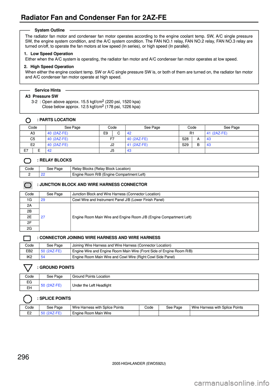
Radiator Fan and Condenser Fan for 2AZ-FE
The radiator fan motor and condenser fan motor operates according to the engine coolant temp. SW, A/C single pressure
SW, the engine system condition, and the A/C system condition. The FAN NO.1 relay, FAN NO.2 relay, FAN NO.3 relay are
turned on/off, to operate the fan motors at low speed (In series), or high speed (In parallel).
1. Low Speed Operation
Either when the A/C system is operating, the radiator fan motor and A/C condenser fan motor operates at low speed.
2. High Speed Operation
When either the engine coolant temp. SW or A/C single pressure SW is, or both of them are turned on, the radiator fan motor
and A/C condenser fan motor operate at high speed.
A3 Pressure SW
3-2 : Open above approx. 15.5 kgf/cm2 (220 psi, 1520 kpa)
Close below approx. 12.5 kgf/cm2 (178 psi, 1226 kpa)
: PARTS LOCATION
CodeSee PageCodeSee PageCodeSee Page
A340 (2AZ-FE)E9C42R141 (2AZ-FE)
C540 (2AZ-FE)F740 (2AZ-FE)S28A43
E240 (2AZ-FE)J241 (2AZ-FE)S29B43
E7E42J543
: RELAY BLOCKS
CodeSee PageRelay Blocks (Relay Block Location)
222Engine Room R/B (Engine Compartment Left)
������ ���: JUNCTION BLOCK AND WIRE HARNESS CONNECTOR
CodeSee PageJunction Block and Wire Harness (Connector Location)
1G29Cowl Wire and Instrument Panel J/B (Lower Finish Panel)
2A
2B
2E27Engine Room Main Wire and Engine Room J/B (Engine Compartment Left)
2F
gg(g)
2G
: CONNECTOR JOINING WIRE HARNESS AND WIRE HARNESS
CodeSee PageJoining Wire Harness and Wire Harness (Connector Location)
EB250 (2AZ-FE)Engine Wire and Engine Room Main Wire (Front Side of Engine Room R/B)
IK254Engine Room Main Wire and Cowl Wire (Right Cowl Side Panel)
: GROUND POINTS
CodeSee PageGround Points Location
EG50 (2AZ FE)Under the Left HeadlightEH50 (2AZ-FE)Under the Left Headlight
: SPLICE POINTS
CodeSee PageWire Harness with Splice PointsCodeSee PageWire Harness with Splice Points
E250 (2AZ-FE)Engine Room Main Wire
System Outline
Service Hints
Page 657 of 2572
2005 HIGHLANDER (EWD592U)
298
Automatic Air Conditioning
10A
HEATER
1K 13
IK4 1
25 413A A1G 8
3A 4
3J 7
IL2 2
A 7A2
IH1 2IL25
IH1 1
21
IH1 3
IAM B 14AMH
B 13AMC
B 12SG- 1
B 11S5- 1
IJ1 1IJ12IJ13IJ14IJ15B 10TP
IJ1 6B 5TE
A14
B
GR
P
O
SB
LG Y- G
Y
LG- R LG- R
P- L P- L
O O
5421 2
4
B 6A
3
B- Y
Y
B Y
BRJ 5
BR O
HR IG+H 9
LG W P- LB
W- B
YY
W
50A HTR
7F 7
4L 74H 7
IC
W- B
I12 W- B
B
I14
1 2
E12VMSI
G- Y
A 17BLW
1 GND
W- BB
3
+B
RB 7BBW- B
ILL+ ILL- ILL- ACC IG BLK STX ILL+ +B 16 12 13 1 2 15 14 6 7
LG- R
LG- R Control Panel
M From Power Source System (
See Page 62)
A10(
A)
, A11(
B)
A/C Control Assembly
Air Mix Control Servo Motor
Blower Motor
Blower Motor
Control
Evapor ator Temp. Sensor
Fusible
Link Block
Heater
Relay
Junction
Connector
Page 659 of 2572

2005 HIGHLANDER (EWD592U)
300
Automatic Air Conditioning
2B
B 1B
5IK332
B- R B
TAM MPD2 MPD1
E 28
BR BR
E2 * 4 : w/o Navigation System * 3 : w/ Navigation System * 2 : 2AZ- FE * 1 : 3MZ- FE
(
*2) (
*1)BR
BR
BR
EE 5B
5A
6 EB2
A 1
2
1
A 3G 5 A17
MPX2 MPX1 22 244
11
BR
BR
V(
*3) G(
*3) R BRP 5
3E 13J 12
G
2A 1A YIB2 8
4F 7
4A 5
IL2 12
B 2
A 9MPX-
Y
IB2 1
IF3 5
A 10
B 6
B 18 B2 2A8
22C 2E3
IK3 18
B 1C 23
IK3 2
1
4
EH A2 13EB2 9
ED A A
J 7
W
J 2 78 MPX1 MPX2
SB
YV
GR G(
*4)
MPX2
MPX1
MPX1
LCK1
BR BRW- B G L
W- L
B- Y A 2
OY-G
Y- G
OMG CLT
Relay IK27
23 15 B- R
MPX+
A 21 9 BIL2 1B 29
SB GR
MPX- MPX+Y
HP MPX2ACMG
Diode
(
Cooling Fan) Y- G
(
*1) B 9(
A)
, B10(
B)
E 6(
B)
, E 7(
E)
, E 9(
C)
A10(
A)
, A11(
B)
S30(
A)
, S31(
B)
Dual
S28(
A)
, S29(
B)
C11(
A)
, C12(
B)
A/C Ambient Temp. Sensor
A/C Magnetic Clutch
A/C Lock Sensor Pr essure SW
A/C Contr ol Assembly
Air bag Sensor
Assembly
Body ECU
Combination MeterEngine Control Module
Gateway ECU
Ju nctio n
ConnectorJunction
Connector Power Window Master SW
with ECU
Short ConnectorShort Connector
E14 : * 1
E 9 : * 2
BR
1 2Engine Coolant
Temp. Sensor E 2
E 19THW
G- B G- B BR
W- B
W- B
BR
(
*2) (
*1) (
*1)(
*2)
Page 663 of 2572
2005 HIGHLANDER (EWD592U)
304
Manual Air Conditioning
50A HTR
7F 7
10A
HEATER
1K 13 1G 8
A A
A
25 413 IK4 1
I 6
OO
A 7
IA 8
423
1 456
II1 5 II1 4 II1 2
I13 1 2II1 1IG1 1
IC 4L 74H 7IG1 21
II16
3F 133J 6
IB 3J 10A 11 3J 73A 4
1K 21G 10
3I 113A 13
A 2A12 A13 IC3 57. 5A
ECU- B
2A 47. 5A
RAD
NO. 2
1K 3
Y
W- B W- B B B W- BWY
BR W BR
GR VBY
B
W- L
VB- Y
BR B W
O B- Y BW- B W- B
R- B
GR
W- B
W- BR
L
BR
W- BY
H 9 J 5
HR IG+ +B ACC
GND
B
LO
HI M2 M1 E
W- B W- B
B 8B 5
B 6
2IL2
MFrom Power Source System (
See Page 62)
A10(
A)
, A11(
B)
A/C Control Assembly
Blower Control SW
Blower Motor
Blower Resistor
Fusible Link
Block
Heater Relay Junction
Connector
Page 666 of 2572
2005 HIGHLANDER (EWD592U)
307
B 29B 2
1B C2323 15 2A8
IK27
2C 22E3
IK3 18 IL2 1
EB2 9
IK3 2
EH A4 1
EE EDA A2 13
A 2
A 3
J 7
J 2B- R Y
SB GR
O
B- YY- G
Y- G
MG CLT
Relay
MPX2
L
W- L G W- B
BR BR BR
(
*2) (
*1)
* 1 : 3MZ- FE
* 2 : 2AZ- FE
PRE LCK1ACMG
Diode
(
Cooling Fan) Y- G
(
*1)
18 BMPX1
B 6
A 10MPX2 MPX1B 9A 21
MPX+ MPX-
OWY
Y
Y
O* 3 : w/ Navigation System
* 4 : w/o Navigation System
E 5(
A)
, E 6(
B)
, E 9(
C)
C11(
A)
, C12(
B)
DualB 9(
A)
, B10(
B)
A/C Magnetic Clutch
A/C Lock Sensor
Pr essure SW
Body ECUCombination Meter
Engine Control Module
Junction
ConnectorJunction
Connector
Page 667 of 2572

2005 HIGHLANDER (EWD592U)
308
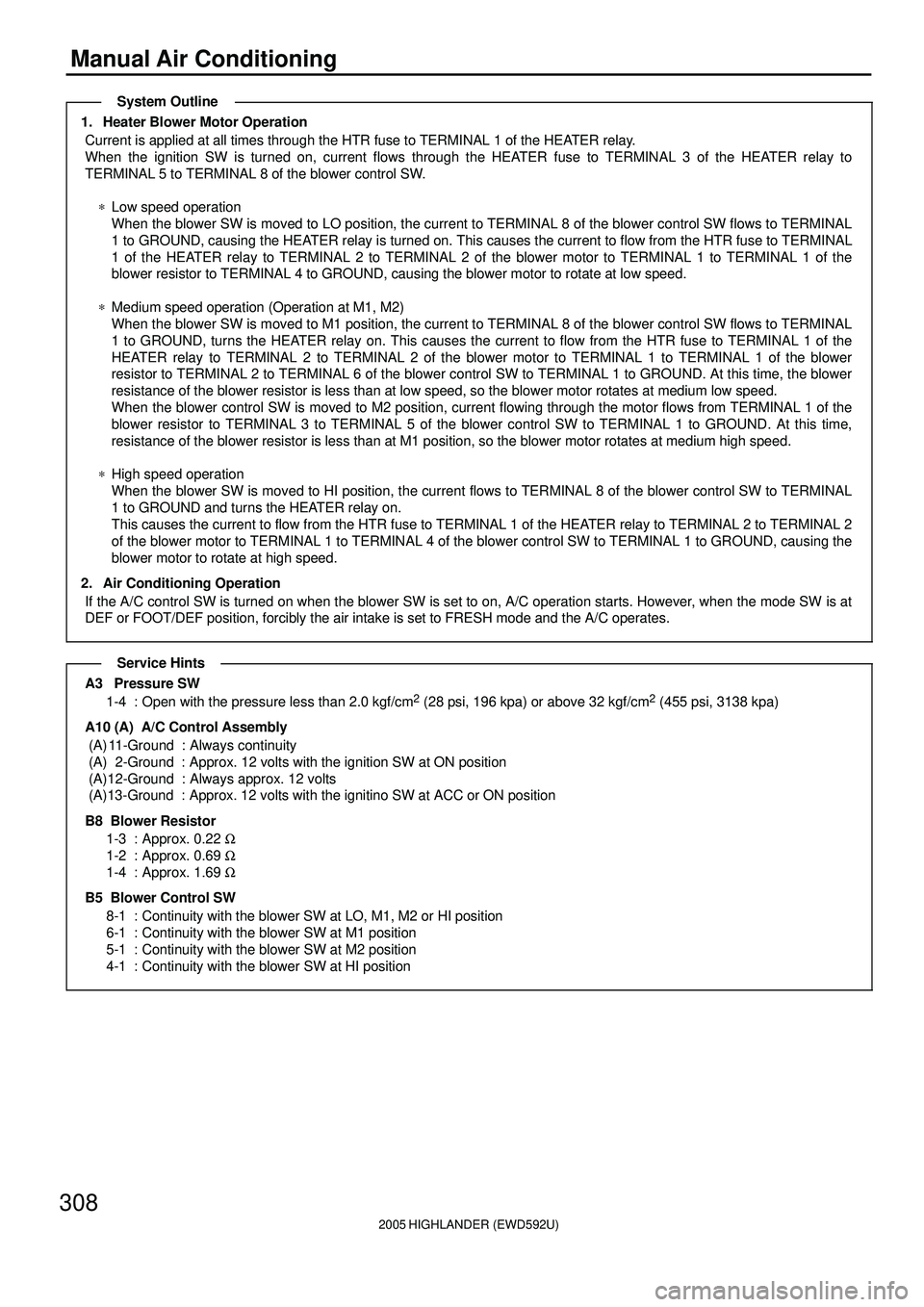
Manual Air Conditioning
1. Heater Blower Motor Operation
Current is applied at all times through the HTR fuse to TERMINAL 1 of the HEATER relay.
When the ignition SW is turned on, current flows through the HEATER fuse to TERMINAL 3 of the HEATER relay to
TERMINAL 5 to TERMINAL 8 of the blower control SW.
*Low speed operation
When the blower SW is moved to LO position, the current to TERMINAL 8 of the blower control SW flows to TERMINAL
1 to GROUND, causing the HEATER relay is turned on. This causes the current to flow from the HTR fuse to TERMINAL
1 of the HEATER relay to TERMINAL 2 to TERMINAL 2 of the blower motor to TERMINAL 1 to TERMINAL 1 of the
blower resistor to TERMINAL 4 to GROUND, causing the blower motor to rotate at low speed.
*Medium speed operation (Operation at M1, M2)
When the blower SW is moved to M1 position, the current to TERMINAL 8 of the blower control SW flows to TERMINAL
1 to GROUND, turns the HEATER relay on. This causes the current to flow from the HTR fuse to TERMINAL 1 of the
HEATER relay to TERMINAL 2 to TERMINAL 2 of the blower motor to TERMINAL 1 to TERMINAL 1 of the blower
resistor to TERMINAL 2 to TERMINAL 6 of the blower control SW to TERMINAL 1 to GROUND. At this time, the blower
resistance of the blower resistor is less than at low speed, so the blower motor rotates at medium low speed.
When the blower control SW is moved to M2 position, current flowing through the motor flows from TERMINAL 1 of the
blower resistor to TERMINAL 3 to TERMINAL 5 of the blower control SW to TERMINAL 1 to GROUND. At this time,
resistance of the blower resistor is less than at M1 position, so the blower motor rotates at medium high speed.
*High speed operation
When the blower SW is moved to HI position, the current flows to TERMINAL 8 of the blower control SW to TERMINAL
1 to GROUND and turns the HEATER relay on.
This causes the current to flow from the HTR fuse to TERMINAL 1 of the HEATER relay to TERMINAL 2 to TERMINAL 2
of the blower motor to TERMINAL 1 to TERMINAL 4 of the blower control SW to TERMINAL 1 to GROUND, causing the
blower motor to rotate at high speed.
2. Air Conditioning Operation
If the A/C control SW is turned on when the blower SW is set to on, A/C operation starts. However, when the mode SW is at
DEF or FOOT/DEF position, forcibly the air intake is set to FRESH mode and the A/C operates.
A3 Pressure SW
1-4 : Open with the pressure less than 2.0 kgf/cm2 (28 psi, 196 kpa) or above 32 kgf/cm2 (455 psi, 3138 kpa)
A10 (A) A/C Control Assembly
(A) 11-Ground : Always continuity
(A) 2-Ground : Approx. 12 volts with the ignition SW at ON position
(A)12-Ground : Always approx. 12 volts
(A)13-Ground : Approx. 12 volts with the ignitino SW at ACC or ON position
B8 Blower Resistor
1-3 : Approx. 0.22 W
1-2 : Approx. 0.69 W
1-4 : Approx. 1.69 W
B5 Blower Control SW
8-1 : Continuity with the blower SW at LO, M1, M2 or HI position
6-1 : Continuity with the blower SW at M1 position
5-1 : Continuity with the blower SW at M2 position
4-1 : Continuity with the blower SW at HI position
System Outline
Service Hints
Page 671 of 2572
2005 HIGHLANDER (EWD592U)
312
Rear Heater
15A
RR HTR
210A
HEATER
2 1
1G 81K13
IK2 2
IA2 11
BH1 9IO118
IR113
B- R O L L
Y Y
B
B Y Y
BL PW
J 5
R25
R26 A A
51
32
3 46
BB BF W- B W- B
W- B
W- BW- B
A
A
AA
R24
IR1 17
GR BR
8 6 5 M
1 2
3IND RLY
E
HI COM DUMMY E
OFF
LO
HI 4
W- B
W- B A
R27
J19
From Power Source System (
See Page 62)
Junction
Connector
Junction
ConnectorRear Heater
Main SW
Rear Heater Blower
Motor
Rear Heater Blower SW
Rear Heater
Relay