Page 616 of 2572
2005 HIGHLANDER (EWD592U)
257
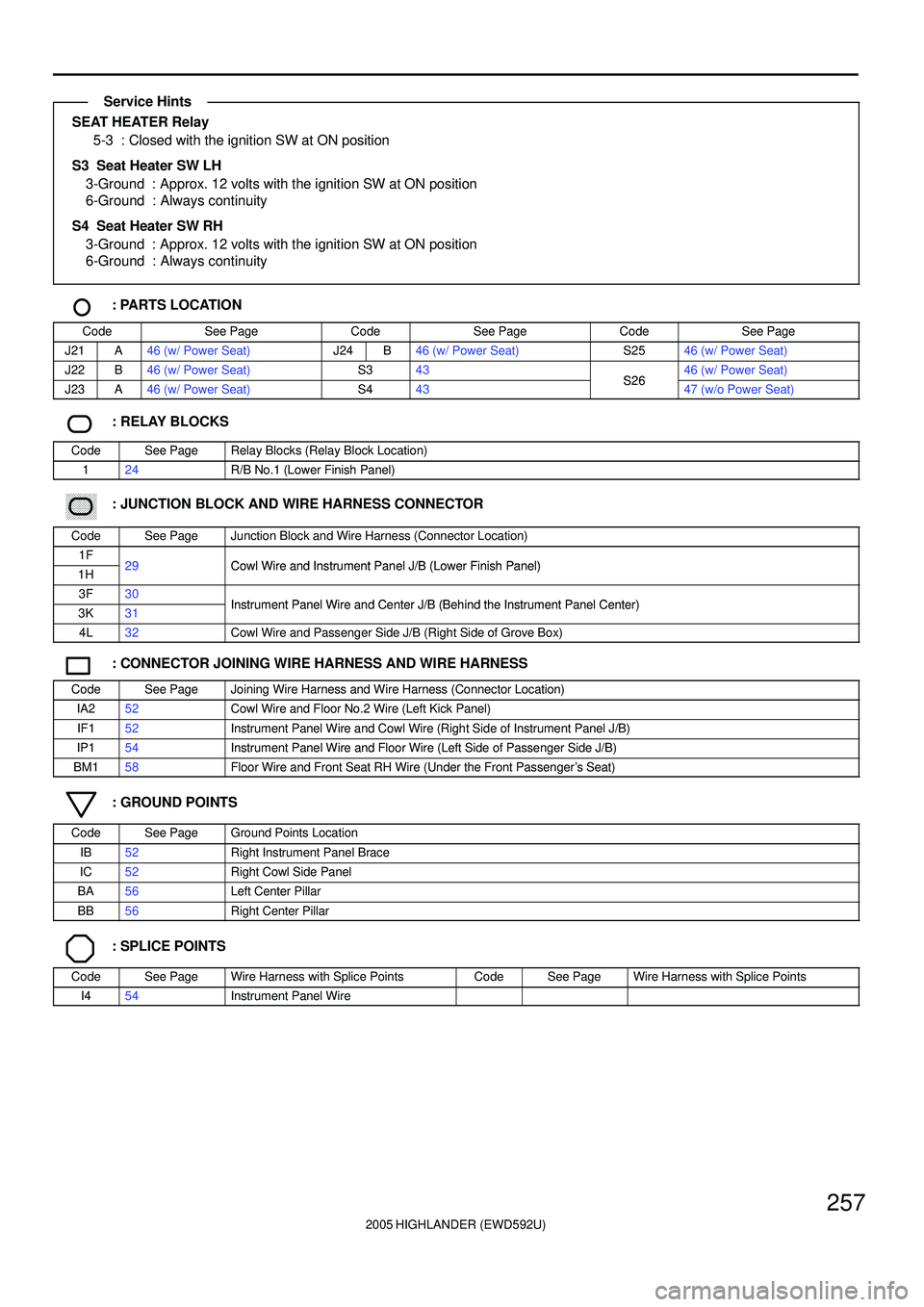
SEAT HEATER Relay
5-3 : Closed with the ignition SW at ON position
S3 Seat Heater SW LH
3-Ground : Approx. 12 volts with the ignition SW at ON position
6-Ground : Always continuity
S4 Seat Heater SW RH
3-Ground : Approx. 12 volts with the ignition SW at ON position
6-Ground : Always continuity
: PARTS LOCATION
CodeSee PageCodeSee PageCodeSee Page
J21A46 (w/ Power Seat)J24B46 (w/ Power Seat)S2546 (w/ Power Seat)
J22B46 (w/ Power Seat)S343S2646 (w/ Power Seat)
J23A46 (w/ Power Seat)S443S2647 (w/o Power Seat)
: RELAY BLOCKS
CodeSee PageRelay Blocks (Relay Block Location)
124R/B No.1 (Lower Finish Panel)
������ ���: JUNCTION BLOCK AND WIRE HARNESS CONNECTOR
CodeSee PageJunction Block and Wire Harness (Connector Location)
1F29Cowl Wire and Instrument Panel J/B (Lower Finish Panel)1H29Cowl Wire and Instrument Panel J/B (Lower Finish Panel)
3F30Instrument Panel Wire and Center J/B (Behind the Instrument Panel Center)3K31Instrument Panel Wire and Center J/B (Behind the Instrument Panel Center)
4L32Cowl Wire and Passenger Side J/B (Right Side of Grove Box)
: CONNECTOR JOINING WIRE HARNESS AND WIRE HARNESS
CodeSee PageJoining Wire Harness and Wire Harness (Connector Location)
IA252Cowl Wire and Floor No.2 Wire (Left Kick Panel)
IF152Instrument Panel Wire and Cowl Wire (Right Side of Instrument Panel J/B)
IP154Instrument Panel Wire and Floor Wire (Left Side of Passenger Side J/B)
BM158Floor Wire and Front Seat RH Wire (Under the Front Passenger's Seat)
: GROUND POINTS
CodeSee PageGround Points Location
IB52Right Instrument Panel Brace
IC52Right Cowl Side Panel
BA56Left Center Pillar
BB56Right Center Pillar
: SPLICE POINTS
CodeSee PageWire Harness with Splice PointsCodeSee PageWire Harness with Splice Points
I454Instrument Panel Wire
Service Hints
Page 622 of 2572

2005 HIGHLANDER (EWD592U)
263
Multiplex communication system (CAN) uses a serial communication protocol and communicates with a differential voltage.
In this network system, TERMINALS CANH and CANL are used for communication between the ECUs and sensors, and
excellent data communication speed and communication error detecting facility are provided. This system is working for the
following system:
*VSC
: PARTS LOCATION
CodeSee PageCodeSee PageCodeSee Page
D342J1944S2741 (2AZ-FE)
J1643S1443Y145
J1743S2739 (3MZ-FE)
: RELAY BLOCKS
CodeSee PageRelay Blocks (Relay Block Location)
222Engine Room R/B (Engine Compartment Left)
������ ���: JUNCTION BLOCK AND WIRE HARNESS CONNECTOR
CodeSee PageJunction Block and Wire Harness (Connector Location)
1D29Cowl Wire and Instrument Panel J/B (Lower Finish Panel)1G29Cowl Wire and Instrument Panel J/B (Lower Finish Panel)
2A27Engine Room Main Wire and Engine Room J/B (Engine Compartment Left)
4C33
4JCowl Wire and Passenger Side J/B (Right Side of Grove Box)4L32Cowl Wire and Passenger Side J/B (Right Side of Grove Box)
4N
: CONNECTOR JOINING WIRE HARNESS AND WIRE HARNESS
CodeSee PageJoining Wire Harness and Wire Harness (Connector Location)
IC352Engine Room Main Wire and Cowl Wire (Left Cowl Side Panel)IC452Engine Room Main Wire and Cowl Wire (Left Cowl Side Panel)
IO254Cowl Wire and Floor Wire (Right Kick Panel)
: GROUND POINTS
CodeSee PageGround Points Location
IC52Right Cowl Side Panel
BB56Right Center Pillar
BF56Near the Rear Side Marker Light RH
System Outline
Page 629 of 2572
2005 HIGHLANDER (EWD592U)
270
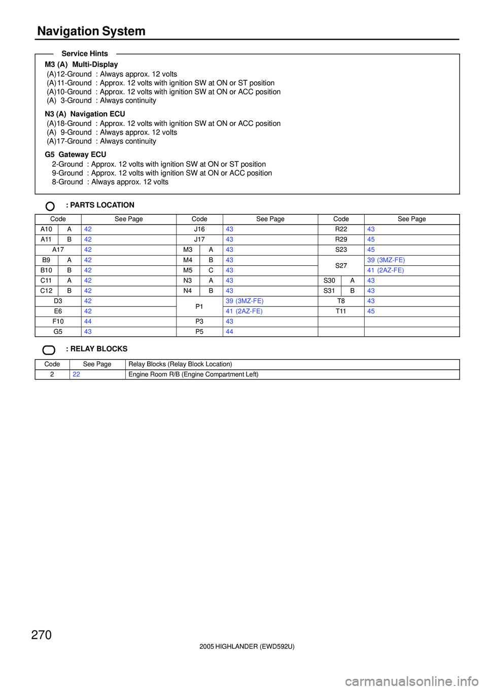
Navigation System
M3 (A) Multi-Display
(A)12-Ground : Always approx. 12 volts
(A) 11-Ground : Approx. 12 volts with ignition SW at ON or ST position
(A)10-Ground : Approx. 12 volts with ignition SW at ON or ACC position
(A) 3-Ground : Always continuity
N3 (A) Navigation ECU
(A)18-Ground : Approx. 12 volts with ignition SW at ON or ACC position
(A) 9-Ground : Always approx. 12 volts
(A)17-Ground : Always continuity
G5 Gateway ECU
2-Ground : Approx. 12 volts with ignition SW at ON or ST position
9-Ground : Approx. 12 volts with ignition SW at ON or ACC position
8-Ground : Always approx. 12 volts
: PARTS LOCATION
CodeSee PageCodeSee PageCodeSee Page
A10A42J1643R2243
A11B42J1743R2945
A1742M3A43S2345
B9A42M4B43S2739 (3MZ-FE)
B10B42M5C43S2741 (2AZ-FE)
C11A42N3A43S30A43
C12B42N4B43S31B43
D342P139 (3MZ-FE)T843
E642P141 (2AZ-FE)T1145
F1044P343
G543P544
: RELAY BLOCKS
CodeSee PageRelay Blocks (Relay Block Location)
222Engine Room R/B (Engine Compartment Left)
Service Hints
Page 637 of 2572
2005 HIGHLANDER (EWD592U)
278
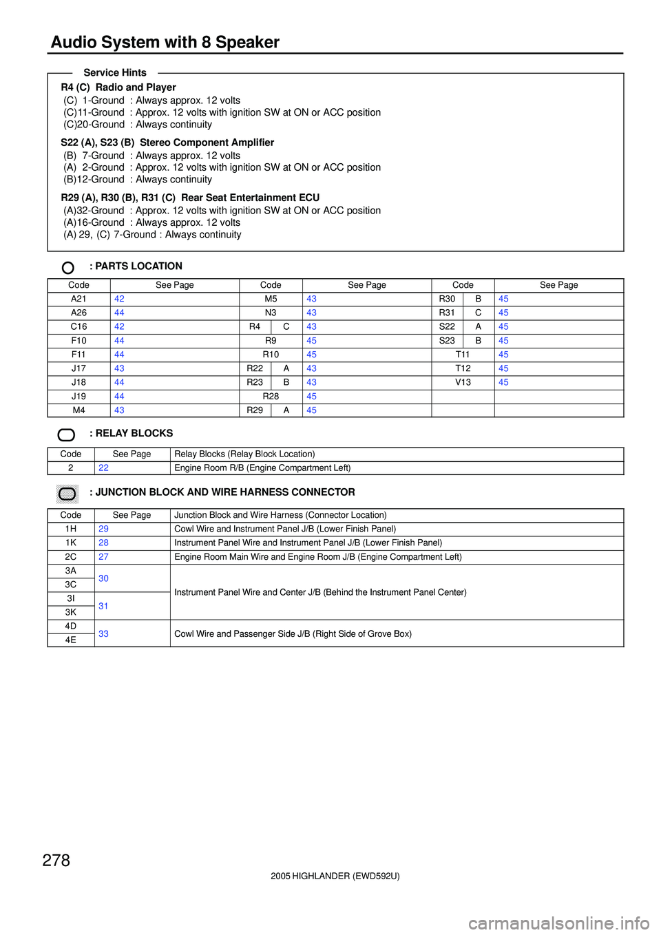
Audio System with 8 Speaker
R4 (C) Radio and Player
(C) 1-Ground : Always approx. 12 volts
(C)11-Ground : Approx. 12 volts with ignition SW at ON or ACC position
(C)20-Ground : Always continuity
S22 (A), S23 (B) Stereo Component Amplifier
(B) 7-Ground : Always approx. 12 volts
(A) 2-Ground : Approx. 12 volts with ignition SW at ON or ACC position
(B)12-Ground : Always continuity
R29 (A), R30 (B), R31 (C) Rear Seat Entertainment ECU
(A)32-Ground : Approx. 12 volts with ignition SW at ON or ACC position
(A)16-Ground : Always approx. 12 volts
(A) 29, (C) 7-Ground : Always continuity
: PARTS LOCATION
CodeSee PageCodeSee PageCodeSee Page
A2142M543R30B45
A2644N343R31C45
C1642R4C43S22A45
F1044R945S23B45
F1144R1045T1145
J1743R22A43T1245
J1844R23B43V1345
J1944R2845
M443R29A45
: RELAY BLOCKS
CodeSee PageRelay Blocks (Relay Block Location)
222Engine Room R/B (Engine Compartment Left)
������ ���: JUNCTION BLOCK AND WIRE HARNESS CONNECTOR
CodeSee PageJunction Block and Wire Harness (Connector Location)
1H29Cowl Wire and Instrument Panel J/B (Lower Finish Panel)
1K28Instrument Panel Wire and Instrument Panel J/B (Lower Finish Panel)
2C27Engine Room Main Wire and Engine Room J/B (Engine Compartment Left)
3A303C30
Instrument Panel Wire and Center J/B (Behind the Instrument Panel Center)3I31
Instrument Panel Wire and Center J/B (Behind the Instrument Panel Center)
3K31
4D33Cowl Wire and Passenger Side J/B (Right Side of Grove Box)4E33Cowl Wire and Passenger Side J/B (Right Side of Grove Box)
Service Hints
Page 647 of 2572
2005 HIGHLANDER (EWD592U)
288
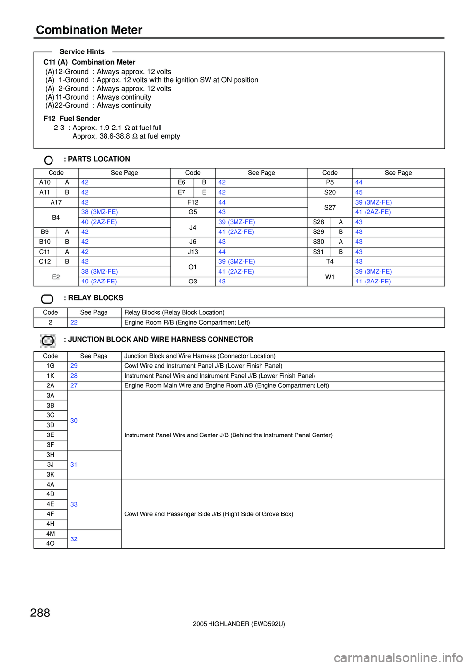
Combination Meter
C11 (A) Combination Meter
(A)12-Ground : Always approx. 12 volts
(A) 1-Ground : Approx. 12 volts with the ignition SW at ON position
(A) 2-Ground : Always approx. 12 volts
(A) 11-Ground : Always continuity
(A)22-Ground : Always continuity
F12 Fuel Sender
2-3 : Approx. 1.9-2.1 W at fuel full
Approx. 38.6-38.8 W at fuel empty
: PARTS LOCATION
CodeSee PageCodeSee PageCodeSee Page
A10A42E6B42P544
A11B42E7E42S2045
A1742F1244S2739 (3MZ-FE)
B438 (3MZ-FE)G543S2741 (2AZ-FE)B440 (2AZ-FE)J439 (3MZ-FE)S28A43
B9A42J441 (2AZ-FE)S29B43
B10B42J643S30A43
C11A42J1344S31B43
C12B42O139 (3MZ-FE)T443
E238 (3MZ-FE)O141 (2AZ-FE)W139 (3MZ-FE)E240 (2AZ-FE)O343W141 (2AZ-FE)
: RELAY BLOCKS
CodeSee PageRelay Blocks (Relay Block Location)
222Engine Room R/B (Engine Compartment Left)
������ ���: JUNCTION BLOCK AND WIRE HARNESS CONNECTOR
CodeSee PageJunction Block and Wire Harness (Connector Location)
1G29Cowl Wire and Instrument Panel J/B (Lower Finish Panel)
1K28Instrument Panel Wire and Instrument Panel J/B (Lower Finish Panel)
2A27Engine Room Main Wire and Engine Room J/B (Engine Compartment Left)
3A
3B
3C303D30
3EInstrument Panel Wire and Center J/B (Behind the Instrument Panel Center)
3F
()
3H
3J31
3K
4A
4D
4E33
4FCowl Wire and Passenger Side J/B (Right Side of Grove Box)
4H
g(g )
4M324O32
Service Hints
Page 649 of 2572
2005 HIGHLANDER (EWD592U)
290
Radiator Fan and Condenser Fan for 3MZ-FE
10A
HEATER
1G 8
72G 62G
25 1322
2
D 22
E 2
2
1 22E 42E 2G 8
2B 3
EH A
EB A 2 3
1 2 2G 3 22
22
140A ALT
30A CDS
30A RDI
F 7
46
15 232
W 4
2
22
2 1
121 B- R
B- R
B- Y
R- Y
W
W
Y R- Y
B- Y B- Y
R- Y W- B W- B
W- B
W- BB- Y
R- Y W- B R- L
Y- G
R- Y L- WR- L R- L
L- Y L- RB- RB- R R- Y
Y
Y
CF
J 4 W 3R 1 A 3
C 5
Battery
FAN NO. 1
Relay FAN NO. 2
Relay FAN NO. 3
Relay 1
52 431
2 FL MAI N
3. 0W
R- Y
EG
W- B
A
A
IK27
B- R
2A8
B- R
J 5
ACMGB 2C8
A 42F 22G
18 IK3
O
M M
EB2 2
EB2 5From Power Source System (
See Page 62)
Single J 2
E 6(
B)
E 9(
C)
Pr essure SW
Condenser Fan
Motor
Diode
(
Cooling Fan)
Engine Control ModuleFusible Link Block
Junction
Connector
Junction
Connector
Junction
Connector
Radiator Fan Motor
Water Temp. SW No. 1 Water Temp. SW No. 2
Page 650 of 2572
2005 HIGHLANDER (EWD592U)
291
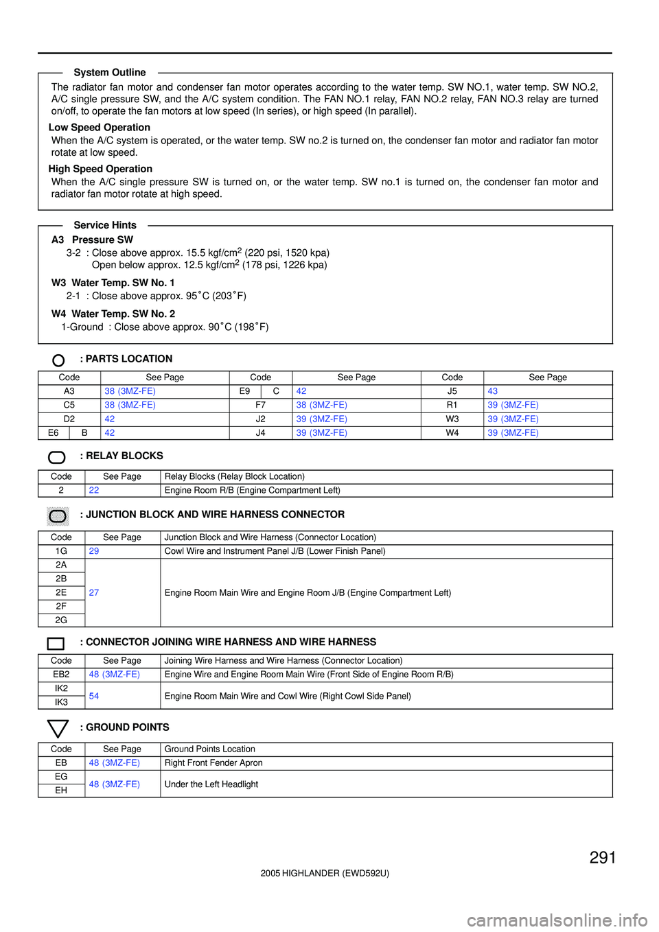
The radiator fan motor and condenser fan motor operates according to the water temp. SW NO.1, water temp. SW NO.2,
A/C single pressure SW, and the A/C system condition. The FAN NO.1 relay, FAN NO.2 relay, FAN NO.3 relay are turned
on/off, to operate the fan motors at low speed (In series), or high speed (In parallel).
Low Speed Operation
When the A/C system is operated, or the water temp. SW no.2 is turned on, the condenser fan motor and radiator fan motor
rotate at low speed.
High Speed Operation
When the A/C single pressure SW is turned on, or the water temp. SW no.1 is turned on, the condenser fan motor and
radiator fan motor rotate at high speed.
A3 Pressure SW
3-2 : Close above approx. 15.5 kgf/cm2 (220 psi, 1520 kpa)
Open below approx. 12.5 kgf/cm2 (178 psi, 1226 kpa)
W3 Water Temp. SW No. 1
2-1 : Close above approx. 95°C (203°F)
W4 Water Temp. SW No. 2
1-Ground : Close above approx. 90°C (198°F)
: PARTS LOCATION
CodeSee PageCodeSee PageCodeSee Page
A338 (3MZ-FE)E9C42J543
C538 (3MZ-FE)F738 (3MZ-FE)R139 (3MZ-FE)
D242J239 (3MZ-FE)W339 (3MZ-FE)
E6B42J439 (3MZ-FE)W439 (3MZ-FE)
: RELAY BLOCKS
CodeSee PageRelay Blocks (Relay Block Location)
222Engine Room R/B (Engine Compartment Left)
������ ���: JUNCTION BLOCK AND WIRE HARNESS CONNECTOR
CodeSee PageJunction Block and Wire Harness (Connector Location)
1G29Cowl Wire and Instrument Panel J/B (Lower Finish Panel)
2A
2B
2E27Engine Room Main Wire and Engine Room J/B (Engine Compartment Left)
2F
gg(g)
2G
: CONNECTOR JOINING WIRE HARNESS AND WIRE HARNESS
CodeSee PageJoining Wire Harness and Wire Harness (Connector Location)
EB248 (3MZ-FE)Engine Wire and Engine Room Main Wire (Front Side of Engine Room R/B)
IK254Engine Room Main Wire and Cowl Wire (Right Cowl Side Panel)IK354Engine Room Main Wire and Cowl Wire (Right Cowl Side Panel)
: GROUND POINTS
CodeSee PageGround Points Location
EB48 (3MZ-FE)Right Front Fender Apron
EG48 (3MZ FE)Under the Left HeadlightEH48 (3MZ-FE)Under the Left Headlight
System Outline
Service Hints
Page 653 of 2572
2005 HIGHLANDER (EWD592U)
294
Radiator Fan and Condenser Fan for 2AZ-FE
30A RDI
6
30A CDS
4
140A ALT
1
W
F 7
WY
51 3222
22
EB2 2
1 225 13
4 22
22 2
2G 32G82B3
2E 2
W- BR- Y
2 3
EH A
L- Y
R- W
W- B
R- YL- R
R- L
L- Y B- R B- RW
R- Y W- B
B- Y
R- Y
R- Y B- R B- RY
B- Y W- B
R- W BatteryFA N
NO. 3
RelayFAN
NO. 2
Relay
C 5
A 3
J 2 FL MAIN
3. 0W
2G 2
2F 4
W- B
W- B M
A
Single
Pressure SWCondenser Fan Motor
Fusible Link Block
Junction
Connector