Page 809 of 2572
F46315
I15
Ignition SWPassenger Side J/B Instrument Panel J/B
ECU-IG
AM1
AM1 IG1
FL MAIN
BatteryW
W1A 1C 1D
1C6 710
1
1 24H 4J42
S27 Skid Control ECU with Actuator
IC41046
32
S27 W-B
EB F7
FL BlockALT2 1Y
B 24B-R GR
GND1 IG1 G
A
J4
J/C
EA W-B
- DIAGNOSTICSABS WITH EBD & BA & TRAC & VSC SYSTEM
05-827
1017 Author�: Date�:
DTC C1241/41 LOW BATTERY POSITIVE VOLTAGE
CIRCUIT DESCRIPTION
DTC No.DTC Detecting ConditionTrouble Area
C1241/41
When any of the following (1 to 2) is detected:
(1) Any of the following conditions continues for at least 10
seconds.
�Vehicle speed is more than 2 mph (3 km/h).
�IG1 terminal voltage is less than 9.5 V.
(2) Any of the following conditions continues for at least 0.2
seconds.
�Solenoid relay remains ON.
�IG1 terminal voltage is less than 9.5 V.
�Relay contact is open.
�Battery
�Charging system
�Power source circuit
WIRING DIAGRAM
05CDC-20
Page 817 of 2572
F46308
Skid Control ECU with Actuator
ABS MTR Relay
ABS CUT Relay
FL MAIN
BatteryS27
S27
S27
S27
ABS2 F7
FL Block ABS R/BR+
MR
BM
MRF 12
3 5
91415 45
5
55
55
555
1
2 35
12
B
W B-OLG
W-L
B-R
G-RB-O
- DIAGNOSTICSABS WITH EBD & BA & TRAC & VSC SYSTEM
05-835
1025 Author�: Date�:
DTC C1251/51 PUMP MOTOR IS LOCKED/OPEN CIRCUIT
IN PUMP MOTOR GROUND
CIRCUIT DESCRIPTION
The ABS pump motor is located inside the brake actuator. The motor is used for BA, TRAC and VSC opera-
tion.
DTC No.DTC Detecting ConditionTrouble Area
C1251/51
�Actuator pump motor does not operate properly.
�Open in actuator pump motor circuit continues for at least
2 sec.�ABS & TRAC actuator
�ABS & TRAC actuator circuit
WIRING DIAGRAM
05F1S-09
Page 818 of 2572

S27
05-836
- DIAGNOSTICSABS WITH EBD & BA & TRAC & VSC SYSTEM
1026 Author�: Date�:
INSPECTION PROCEDURE
HINT:
Start the inspection from step 1 in c")
G24767GND2
Skid Control ECU
(harness side connector)
S27
05-836
- DIAGNOSTICSABS WITH EBD & BA & TRAC & VSC SYSTEM
1026 Author�: Date�:
INSPECTION PROCEDURE
HINT:
Start the inspection from step 1 in case of using the hand-held tester and start from step 2 in case of not
using the hand-held tester.
1 PERFORM ACTIVE TEST BY HAND-HELD TESTER(ABS MOTOR RELAY
OPERATION)
(a) Connect the hand-held tester to the DLC3.
(b) Start the engine.
(c) Select the ACTIVE TEST mode on the hand-held tester.
(d) Check the operation sound of the ABS motor individually when operating it with the hand-held tester.
ItemVehicle Condition / Test DetailsVehicle Condition / Test Details
ABS MOT RELAYABS motor relay / ON or OFFON: Motor relay ON
OK:
The operation sound of the ABS motor should be heard.
NG Go to step 2
OK
REPLACE ABS & TRACTION ACTUATOR ASSY (SEE PAGE 32-37)
2 INSPECT HARNESS AND CONNECTOR(GND2 OF SKID CONTROL ECU AND
BODY GROUND)
(a) Disconnect the skid control ECU connector.
(b) Measure the resistance according to the value(s) in the
table below.
Standard:
Tester ConnectionSpecified Condition
S27-1 (GND2) - Body groundBelow 1 W
NG REPAIR OR REPLACE HARNESS OR
CONNECTOR
OK
REPLACE ABS & TRACTION ACTUATOR ASSY (SEE PAGE 32-37)
Page 838 of 2572
A88701
EH FL
MainEFI NO. 2
2IK313 2D
5
3
5P-L
BatteryEFI RelayEngine Room R/B No. 2
WEngine Room J/B
1ECM
MREL
E58
E7E1 1 B
BR
A
AJ7
J/C
BR
EDACIS
E7 15
R-Y V2
VSV for IAC
Valve No. 2
12 B-R B-W1
EB1 2 2
2 1
Y
3
14EFI NO. 1
2I 2F2B
W 3
1F7
FL Block
Assy
A
J2
J/C W-B
- DIAGNOSTICSSFI SYSTEM (3MZ-FE)
05-661
851 Author�: Date�:
2005 HIGHLANDER REPAIR MANUAL (RM1144U)
WIRING DIAGRAM
Page 840 of 2572

Y
A85675
A81699A87763
Wire Harness Side
V2
VSV for IAC Valve No. 2
E7
ECM
ACIS
A85448
A90291A92391
Wire Harness Side
V2
VSV for IAC Valve No. 2
EFI Relay
Engine Room J/B
- DIAGNOSTICSSFI SYSTEM (3MZ-FE)
05-663
853 Author�: Date�:
2005 HIGHLANDER REPAIR MANUAL (RM1144U)
3 CHECK WIRE HARNESS (VSV FOR IAC VALVE NO. 2 - ECM, VSF FOR IAC VALVE
NO. 2 - EFI RELAY)
(a) Check the wire harness between the VSV and ECM.
(1) Disconnect the V2 VSV connector.
(2) Disconnect the E7 ECM connector.
(3) Check the resistance of the wire harness side con-
nectors.
Standard:
Tester ConnectionSpecified Condition
V2-2 - E7-15 (ACIS)Below 1 W
V2-2 or E7-15 (ACIS) - Body ground10 kW or higher
(b) Check the wire harness between the VSV and EFI relay.
(1) Disconnect the V2 VSV connector.
(2) Remove the EFI relay from the engine room J/B.
(3) Check the resistance of the wire harness side con-
nectors.
Standard:
Tester ConnectionSpecified Condition
V2-1 - J/B EFI relay terminal 3Below 1 W
NG REPAIR OR REPLACE HARNESS AND
CONNECTOR
OK
Page 843 of 2572

Y
A85675
A81699A87763
Wire Harness Side
V2
VSV for IAC Valve No. 2
E7
ECM
ACIS
A85448
A90291A92391
Wire Harness Side
V2
VSV for IAC Valve No. 2
EFI Relay
Engine Room J/B
05-666
- DIAGNOSTICSSFI SYSTEM (3MZ-FE)
856 Author�: Date�:
2005 HIGHLANDER REPAIR MANUAL (RM1144U)
3 CHECK WIRE HARNESS (VSV FOR IAC VALVE NO. 2 - ECM, VSV FOR IAC VALVE
NO.2 - EFI RELAY)
(a) Check the wire harness between the VSV and ECM.
(1) Disconnect the V2 VSV connector.
(2) Disconnect the E7 ECM connector.
(3) Check the resistance of the wire harness side con-
nectors.
Standard:
Tester ConnectionSpecified Condition
V2-2 - E7-15 (ACIS)Below 1 W
V2-2 or E7-15 (ACIS) - Body ground10 kW or higher
(b) Check the wire harness between the VSV and EFI relay.
(1) Disconnect the V2 VSV connector.
(2) Remove the EFI relay from the engine room J/B.
(3) Check the resistance OF the wire harness side con-
nectors.
Standard:
Tester ConnectionSpecified Condition
V2-1 (VSV for ACIS) - J/B EFI relay terminal 3Below 1 W
NG REPAIR OR REPLACE HARNESS AND
CONNECTOR
OK
Page 845 of 2572
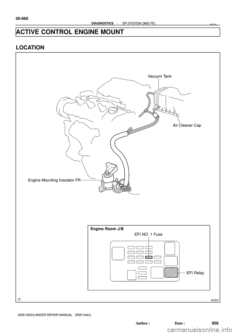
A87847
EFI Relay EFI NO. 1 Fuse Engine Room J/B
Vacuum Tank
Engine Mounting Insulator FR
Air Cleaner Cap
05-668
- DIAGNOSTICSSFI SYSTEM (3MZ-FE)
858 Author�: Date�:
2005 HIGHLANDER REPAIR MANUAL (RM1144U)
ACTIVE CONTROL ENGINE MOUNT
LOCATION
05EXI-05
Page 846 of 2572
A88702
EH FL
MainEFI NO. 2
2IK313 2D
5
3
5P-L
BatteryEFI RelayEngine Room R/B No. 2
WEngine Room J/B
1ECM
MREL
E58
BY-G V5
VSV for ACM
27
B B-W
1EB2 2 2
2 1
Y
3
14EFI NO. 1
2I 2F2B
W 3
1F7
FL Block
Assy
A
J2
J/C W-BACM 6
E9
- DIAGNOSTICSSFI SYSTEM (3MZ-FE)
05-669
859 Author�: Date�:
2005 HIGHLANDER REPAIR MANUAL (RM1144U)
CIRCUIT DESCRIPTION
The Active Control Engine Mount (ACM) system decreases engine vibration at low engine speed using the
VSV for ACM. The VSV is controlled by a pulse signal transmitted to the VSV from the ECM. The frequency
of this pulse signal is matched to the engine speed to decrease engine vibration.
WIRING DIAGRAM