Page 1366 of 2572
E74078
Instrument Panel J/B
TAILLIGHT RelayBody ECU
F3
Front Parking Lamp LH
F4
Front Parking Lamp RH
R8 Taillamp RH
(Rear Combination Lamp RH)
R7 Taillamp LH
(Rear Combination Lamp LH)
R15
Rear Side Marker Lamp RH
R14
Rear Side Marker Lamp LH
L1
License Plate Lamp
F7
FL Block
FL MAIN BatteryTAILTRLY
ALT7
B9 4
1J
4
1B
11
1B 1
1A
4
1HSB
IA1
BG2
BE BCEA
EG J14
J/CJ3
J/CJ1
J/C G
G 12
3
5 B
W
46B E
46
B E
12
21 E E
W2 8
E
EB
B
A A A
1 2 2 1W-B
W-B
W-B
BR
W-B
BR
BR
W-B
W-B BR
W-B BR
BR
W-B J13
J/CJ12
J/C 12
12
W
- DIAGNOSTICSLIGHTING SYSTEM
05-1575
1765 Author�: Date�:
2005 HIGHLANDER REPAIR MANUAL (RM1144U)
WIRING DIAGRAM
Page 1367 of 2572
05-1576
- DIAGNOSTICSLIGHTING SYSTEM
1766 Author�: Date�:
2005 HIGHLANDER REPAIR MANUAL (RM1144U)
INSPECTION PROCEDURE
1 PERFORM ACTIVE TEST USING HAND-HELD TESTER
(a) Connect the hand-held tester to the DLC3.
(b) Turn the ignition switch to the ON position and turn the hand-held tester main switch on.
(c) Select the item below in the ACTIVE TEST and then check the relay operation.
BODY NO.1 (MULTIPLEX NETWORK BODY ECU):
ItemTest DetailsDiagnostic Note
TAIL LIGHTTaillamp relay ON/OFF-
OK: Taillamp comes on.
NG Go to step 2
OK
PROCEED TO NEXT CIRCUIT INSPECTION SHOWN IN PROBLEM SYMPTOMS TABLE
(SEE PAGE 05-1538)
Page 1394 of 2572
(From August, 2004)
236 Author�: Date�:
HINT:
*: If no conditions are specifically stated for ºldlingº, the shift lever is in the N or P position, the A/C switc")
05-46
- DIAGNOSTICSSFI SYSTEM (2AZ-FE)(From August, 2004)
236 Author�: Date�:
HINT:
*: If no conditions are specifically stated for ºldlingº, the shift lever is in the N or P position, the A/C switch
is OFF and all accessory switches are OFF.
2. ACTIVE TEST
HINT:
Performing the hand-held tester ACTIVE TEST allows relay, VSV, actuator and other items to be operated
without removing any parts. Performing the ACTIVE TEST early in troubleshooting is one way to shorten
labor time. The DATA LIST can be displayed during the ACTIVE TEST.
(a) Warm up the engine.
(b) Turn the ignition switch OFF.
(c) Connect the hand-held tester or the OBD II scan tool to the DLC3.
(d) Turn the ignition switch ON.
(e) Turn ON the hand-held tester or the OBD II scan tool.
(f) Enter the following menus: DIAGNOSIS / ENHANCED OBD II / ACTIVE TEST.
(g) According to the display on tester, perform the ºACTIVE TEST.
Hand-held Tester DisplayTest DetailsDiagnostic Note
INJ VOL
[Test Details]
Control injection volume
Minimum: -12.5 %, Maximum: 25 %
[Vehicle Condition]
Engine speed: 3000 rpm or less�All injectors are tested at once
�Injection volume is gradually
changed between -12.5 and 25
%
A/F CONTROL
[Test Details]
Control injection volume
-12.5 or 25 % (change the injection volume -12.5 % or 25 %)
[Vehicle Condition]
Engine speed: 3000 rpm or less
Following A/F CONTROL proce-
dure enables technician to check
and graph voltage outputs of both
A/F sensor and heated oxygen
sensor
For displaying the graph, enter
ºACTIVE TEST / A/F CONTROL /
USER DATAº, select ºAFS B1S1
and O2S B1S2º by pressing ºYESº
and push ºENTERº, Then press
ºF4º
EVAP VSV (ALONE)
[Test Details]
Activate EVAP VSV control
ON or OFF
-
A/C MAG CLUTCH
[Test Details]
Control A/C magnet clutch
ON or OFF
-
FUEL PUMP / SPD
[Test Details]
Control fuel pump
ON or OFF
-
VCUUM PUMP (ALONE)
[Test Details]
Vacuum pump
ON or OFF
-
VENT VALVE (ALONE)
[Test Details]
Vent valve
ON or OFF
-
VVT CTRL B1
[Test Details]
Activate VVT system (Bank 1)
ON or OFF�ON: Rough idle or engine stall
�OFF: Normal engine speed
TC/TE1
[Test Details]
Connect TC and TE1
ON or OFF
-
FC IDL PROHBT
[Test Details]
Control idle fuel cut prohibit
ON or OFF
-
Page 1400 of 2572
(From August, 2004)
600 Author�: Date�:
Hand-held Tester DisplayDiagnostic Note Normal Condition * Measurement Item/Range
(Display)
EVAP VSVVSV status for EVAP c")
05-410
- DIAGNOSTICSSFI SYSTEM (3MZ-FE)(From August, 2004)
600 Author�: Date�:
Hand-held Tester DisplayDiagnostic Note Normal Condition * Measurement Item/Range
(Display)
EVAP VSVVSV status for EVAP control/
ON or OFFVSV operating: ONEVAP VSV is controlled by the
ECM (ground side duty control)
BOOST PRESS VSV
VSV status for boost pressure
control/
ON or OFF
VSV operating: ON'
IGNITIONIgnition counter/ Minimum: 0, Max-
imum: 6000 to 600'
CYL #1, #2, #3, #4, #5, #6Misfire ratio of cylinder 1 to 6/
Minimum: 0 %, Maximum: 50 %0 %This item is displayed in only idling
MISFIRE LOAD
Engine load for first misfire range/
Minimum: 0 g/rev, Maximum: 3.98
g/rev.
Misfire 0: 0 g/rev.'
MISFIRE RPM
Engine RPM for first misfire range/
Minimum: 0 rpm, Maximum: 6,375
rpm
Misfire 0: 0 rpm'
FC TAUFuel Cut TAU: Fuel cut during very
light load/ ON or OFFFuel cut operating: ON
Fuel cut is being performed under
very light load to prevent engine
combustion from becoming incom-
plete
CHECK MODECheck mode/ ON or OFFCheck mode ON: ONSee step 3
HINT:
*: If no conditions are specifically stated for ºldlingº, the shift lever is in the N or P position, the A/C switch
is OFF and all accessory switches are OFF.
2. ACTIVE TEST
HINT:
Performing the hand-held tester ACTIVE TEST allows relay, VSV, actuator and other items to be operated
without removing any parts. Performing the ACTIVE TEST early in troubleshooting is one way to shorten
labor time. The DATA LIST can be displayed during the ACTIVE TEST.
(a) Warm up the engine.
(b) Turn the ignition switch OFF.
(c) Connect the hand-held tester or the OBD II scan tool to the DLC3.
(d) Turn the ignition switch ON.
(e) Turn ON the hand-held tester or the OBD II scan tool.
(f) Enter the following menus: DIAGNOSIS / ENHANCED OBD II / ACTIVE TEST.
(g) According to the display on tester, perform the ºACTIVE TESTº.
Hand-held Tester DisplayTest DetailsDiagnostic Note
INJ VOL
[Test Details]
Control injection volume
Minimum: -12.5 %, Maximum: 25 %
[Vehicle Condition]
Engine speed: 3,000 rpm or less�All injectors are tested at once
�Injection volume is gradually
changed between -12.5 and 25
%
A/F CONTROL
[Test Details]
Control injection volume
-12.5 or 25 % (change injection volume -12.5 % or 25 %)
[Vehicle Condition]
Engine speed: 3,000 rpm or less
Following A/F CONTROL proce-
dure enables technician to check
and graph voltage outputs of both
the A/F sensor and heated oxygen
sensor
For displaying graph, enter ºAC-
TIVE TEST / A/F CONTROL /
USER DATAº, select ºAFS B1S1
and O2S B1S2º by pressing ºYESº
and push ºENTERº. Then press
ºF4º
Page 1407 of 2572
A90306
I15
Ignition
Switch
EE W-BIK2 AM2IGN1 Instrument Panel J/B Assy
E5
E9ECM
BatteryFL
MainEFI
NO. 1
4
W9
1 4E
1
E5
1 10GR
3
21 5EFI Relay
EHBR
BR AAP
Engine Room J/B
J7
J/C 2FIGSW
+B
E1 B EJ6
J/C
MRELE58
P-LE P 4
4M 6
1G 1
1CPassenger Side J/B
W
J2
J/C A W1
2I4
2B
5
2BW
W 10
IK313 IC1 1AM2 IG2
F7
FL Block AssyY
L-Y6
7
3 05-312
- DIAGNOSTICSSFI SYSTEM (2AZ-FE)
502 Author�: Date�:
2005 HIGHLANDER REPAIR MANUAL (RM1144U)
ECM POWER SOURCE CIRCUIT
CIRCUIT DESCRIPTION
When the ignition switch is turned ON, battery voltage is applied to terminal IGSW of the ECM. The ECM
ºMRELº output signal causes current to flow to the coil, closing the contacts of the EFI relay (Marking: EFI)
and supplying power to terminal +B of the ECM.
If the ignition switch is turned OFF, the ECM holds the EFI relay ON for a maximum of 2 seconds to allow
for the initial setting of the throttle valve.
WIRING DIAGRAM
05EVZ-05
Page 1410 of 2572
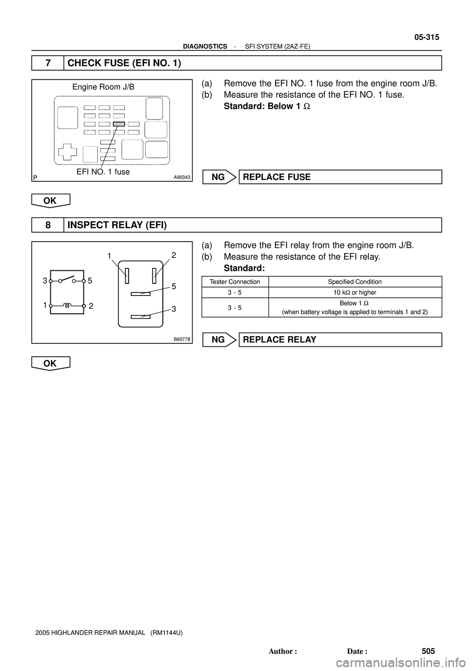
A90343
Engine Room J/B
EFI NO. 1 fuse
B60778
5
1
2 312
5
3
- DIAGNOSTICSSFI SYSTEM (2AZ-FE)
05-315
505 Author�: Date�:
2005 HIGHLANDER REPAIR MANUAL (RM1144U)
7 CHECK FUSE (EFI NO. 1)
(a) Remove the EFI NO. 1 fuse from the engine room J/B.
(b) Measure the resistance of the EFI NO. 1 fuse.
Standard: Below 1 W
NG REPLACE FUSE
OK
8 INSPECT RELAY (EFI)
(a) Remove the EFI relay from the engine room J/B.
(b) Measure the resistance of the EFI relay.
Standard:
Tester ConnectionSpecified Condition
3 - 510 kW or higher
3 - 5Below 1 W
(when battery voltage is applied to terminals 1 and 2)
NG REPLACE RELAY
OK
Page 1411 of 2572

506 Author�: Date�:
2005 HIGHLANDER REPAIR MANUAL (RM1144U)
9 CHECK WIRE HARNESS")
A90291
A67445
A92643
EFI Relay Wire Harness Side
E5
ECM
MREL
Engine Room J/B
05-316
- DIAGNOSTICSSFI SYSTEM (2AZ-FE)
506 Author�: Date�:
2005 HIGHLANDER REPAIR MANUAL (RM1144U)
9 CHECK WIRE HARNESS (EFI RELAY - ECM, EFI RELAY - BODY GROUND)
(a) Check the wire harness between the EFI relay and ECM.
(1) Remove the EFI relay from the engine room J/B.
(2) Disconnect the E5 ECM connector.
(3) Measure the resistance of the wire harness side
connectors.
Standard:
Tester ConnectionSpecified Condition
J/B EFI relay terminal 1 - E5-8 (MREL)Below 1 W
J/B EFI relay terminal 1 or E5-8 (MREL) - Body ground10 kW or higher
(b) Check the wire harness between the EFI relay and body
ground.
(1) Remove the EFI relay from the engine room J/B.
(2) Measure the resistance of the wire harness side
connector and the body ground.
Standard:
Tester ConnectionSpecified Condition
J/B EFI relay terminal 2 - Body groundBelow 1 W
OK REPAIR OR REPLACE HARNESS AND
CONNECTOR
NG
CHECK AND REPAIR HARNESS AND CONNECTOR (TERMINAL +B OF ECM - BATTERY POS-
ITIVE TERMINAL)
Page 1419 of 2572
A97611
Pump Module (fig. 1)
Condition: Purge FlowCondition: Leak Check
From Refueling Valve
To Air Filter
(Atmosphere)
Vacuum Pump: OFFVent Valve: OFF
(vent)
Pressure Sensor 0.02 Inch Orifice
Canister
: Airflow
Vacuum Pump: ON
Vent Valve: ON
(closed)
A71562
Pressure Sensor Specification (fig. 2)
Output Voltage
Usable Range
4.900 V
4.150 V
1.425 V
0.450 V
Malfunction Area
Pressure
60
kPa11 0
kPa
Malfunction Area
Standard atmospheric pressure is 101.3 kPaHINT:
A85251
Soak Timer Circuit (fig. 3)
Ignition Switch
IGSW
Power
ECM
EFI MAIN
MREL+B
15 ASource IC
Soak Timer IC Main Relay
Control IC
Battery
- DIAGNOSTICSSFI SYSTEM (2AZ-FE)
05-321
511 Author�: Date�:
2005 HIGHLANDER REPAIR MANUAL (RM1144U)

R7 Taillamp LH
(Rear Combination Lamp LH)
R15
Rear Side")


Condition: Purge FlowCondition: Leak Check
From Refueling Valve
To Air Filter
(Atmosphere)
Vacuum Pump: OFFVent Valve: OFF
(vent)
Pressure Sensor 0.02 Inch Orifice
Canister")