Page 500 of 2572
2005 HIGHLANDER (EWD592U)
185
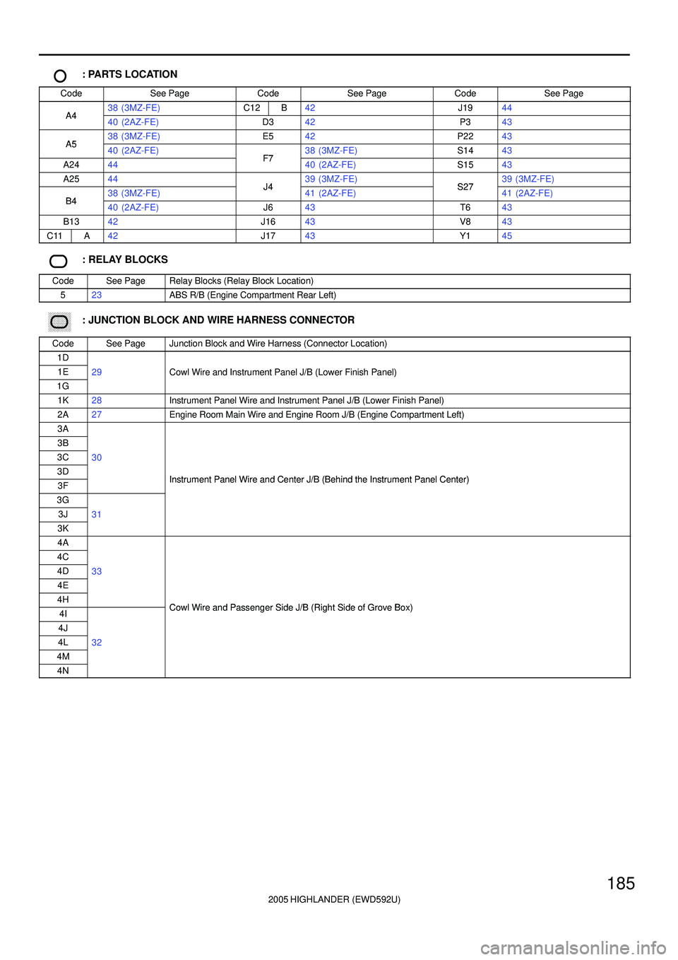
: PARTS LOCATION
CodeSee PageCodeSee PageCodeSee Page
A438 (3MZ-FE)C12B42J1944A440 (2AZ-FE)D342P343
A538 (3MZ-FE)E542P2243A540 (2AZ-FE)F738 (3MZ-FE)S1443
A2444F740 (2AZ-FE)S1543
A2544J439 (3MZ-FE)S2739 (3MZ-FE)
B438 (3MZ-FE)J441 (2AZ-FE)S2741 (2AZ-FE)B440 (2AZ-FE)J643T643
B1342J1643V843
C11A42J1743Y145
: RELAY BLOCKS
CodeSee PageRelay Blocks (Relay Block Location)
523ABS R/B (Engine Compartment Rear Left)
������ ���: JUNCTION BLOCK AND WIRE HARNESS CONNECTOR
CodeSee PageJunction Block and Wire Harness (Connector Location)
1D
1E29Cowl Wire and Instrument Panel J/B (Lower Finish Panel)
1G
()
1K28Instrument Panel Wire and Instrument Panel J/B (Lower Finish Panel)
2A27Engine Room Main Wire and Engine Room J/B (Engine Compartment Left)
3A
3B
3C30
3DInstrument Panel Wire and Center J/B (Behind the Instrument Panel Center)3FInstrument Panel Wire and Center J/B (Behind the Instrument Panel Center)
3G
3J31
3K
4A
4C
4D33
4E
4HCowl Wire and Passenger Side J/B (Right Side of Grove Box)4ICowl Wire and Passenger Side J/B (Right Side of Grove Box)
4J
4L32
4M
4N
Page 525 of 2572
2005 HIGHLANDER (EWD592U)
210
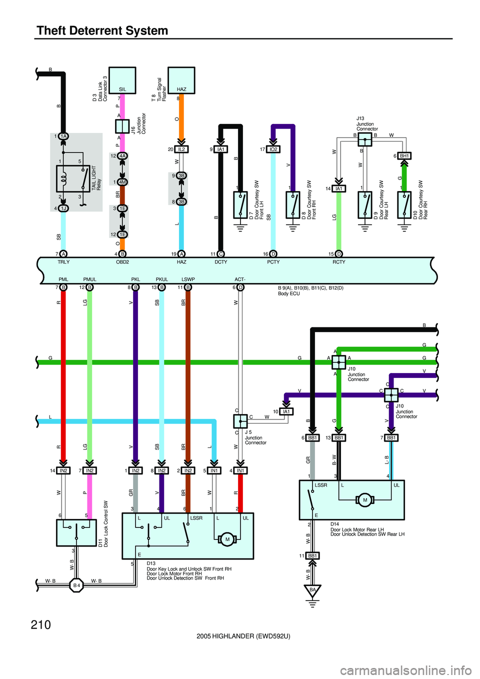
Theft Deterrent System
11
D 15 1
RCTY
LGTAI L LI GHT
Relay
4A 12
4M 1
1E 3
1E 12
B 4
OBD2SIL
OBR
7
P
B 45 6
3 IN2 14 IN27 B 7PML
B 12PMUL
1IN2 IN28IN22IN15IN14C C B 8PKL
B 13PKUL LSWP
11 B D6ACT-
R
LG
V
SB
BR
W W W
P
GR
V
BR
W
R
34612IA1 10
C
D11
J 5
D13LSSR UL LW
BB1 6 BB113 BB17 A A
C C
13 4
BA BB1 11
W- B W- B
2
GR
B- W
L- BB
G
V
CC AA
J10 J10
D14B
G
G
V
V G
V
5
W- B W- BG
L
W- BR
LG
V
SB
BR
L
LUL
EMM 3B 9
3B 8
A 19
HAZ HAZ
LW
8
IL2 20
O
A 7
SB
TRL YC 11
DCTY
B
D 16
PCTY
SB
LSSR L UL
E
D 7
D 8
1J 423 151A 1
D 9
1
D10
BH1 6 B B
BB
V
W
GB
W B
A A
P
J16
IA1 14
D 3
T 8
W
IA1 9IO217
B 9(
A)
, B10(
B)
, B11(
C)
, B12(
D)
Body ECU
Data Link
Connector 3
Door Courtesy SW
Front LH
Door Courtesy SW
Front RH
Door Courtesy SW
Rear LH
Door Courtesy SW
Rear RH Door Lock Control SW
Door Key Lock and Unlock SW Front RH
Door Lock Motor Front RH
Door Unlock Detection SW Front RHDoor Lock Motor Rear LH
Door Unlock Detection SW Rear LH Junction
ConnectorJunction
Connector Junction
Connector
Junction
Connector
Turn Signal
Flasher
J13
Junction
Connector
Page 526 of 2572
2005 HIGHLANDER (EWD592U)
211
E D 11
ILE
BR
B
G
G
V
VD 17LSWA
A A
BH1 17
BC1 11 BH1 8
BC1 6 BH1 15
BC1 7
B
G BR
SB
V GR
B- W
L- B
412 AA
V
BB BC1 133
W- B W- B
BG3 8BG21BG23
BE A 412
V
G
RGB
V W- B
3B15 J12
B
IC 4L 74H 11 4G 9D 7GND1
D DB 2KSW
1 2
G G W- B
W- B W- BJ 6 K 4
MM
D1510A
HORN
32 51
D 10IC2 42B 6
HORN
W- R P
HORN
Relay40A
MAIN
2G 4
C 3
R
5 R- B
HRLY 2
EACT- ACT+ LSSR SLUL
L- R
3 3
1 3
2
3
IK3 4DRL NO. 2
Relay E10
4J 5
4F 26 2
4H 6
4D 1210A
DOME
2A 3
12 IK3
G
Y
C 6BCTY
G
IA1 4
BG3 4
GR R
1 2
W- B
R12R
IA13
BB
4N 1
W- B
J14
A 23 14
2B 1HEAD
LAMP
Relay
R- B
(
*3)
R- B
(
*3) L- R
(
*4)
L- R
(
*4)(
*3)
(
*3)
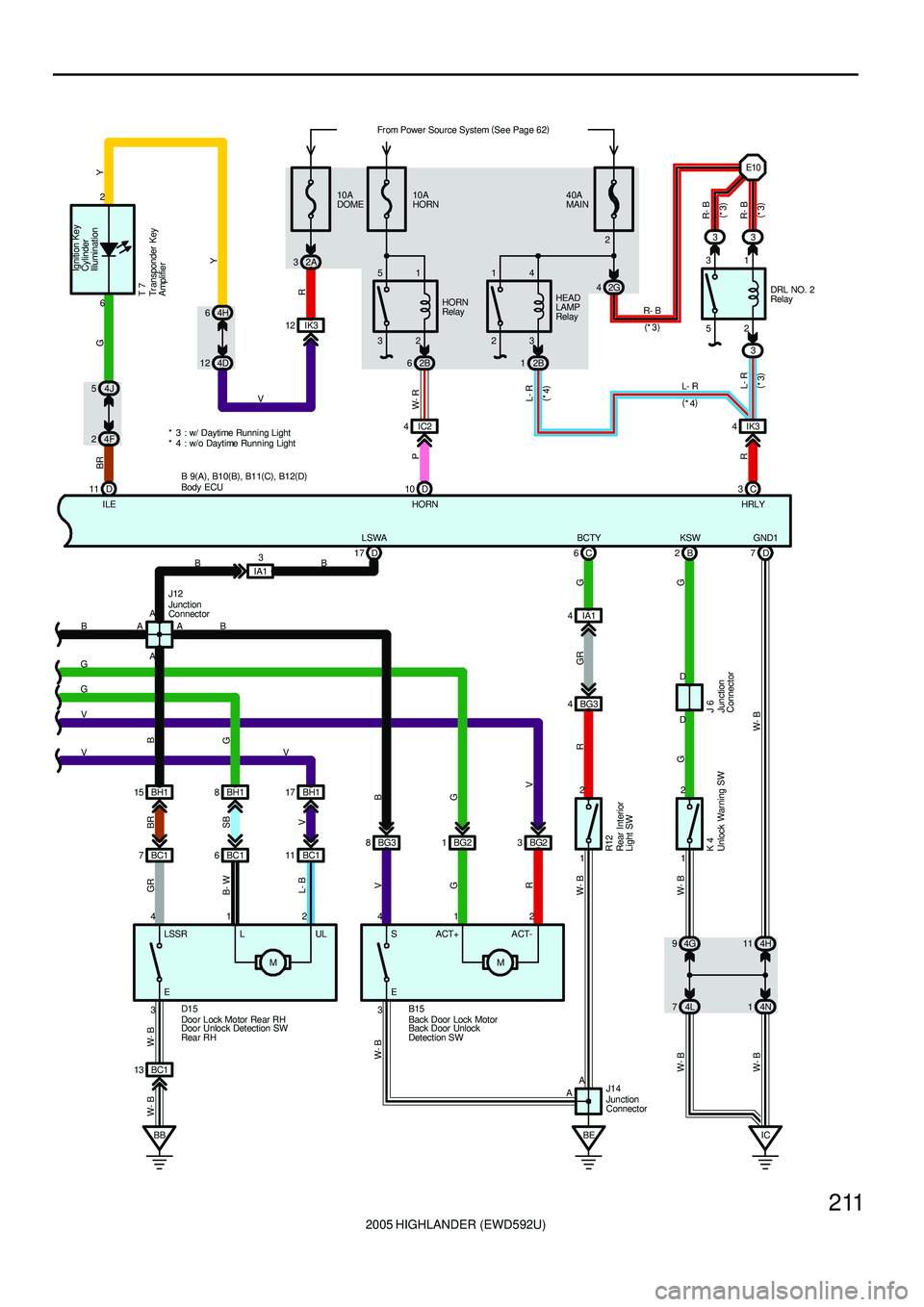
* 3 : w/ Daytime Runni ng Light
* 4 : w/o Daytime Running LightFr om Power Source System (
See Page 62)
B 9(
A)
, B10(
B)
, B11(
C)
, B12(
D)
Igniti on Key
Cylinder
Illumination
Y
V
Body ECU
Back Door Lock Motor
Back Door Unlock
Detection SW Door Lock Motor Rear RH
Door Unlock Detection SW
Rear RH
Junction
Connector
Junction
Connector
Junction
Connector
Unlock Warning SW Rear Interior
Light SWTr ansponder Key
Amplifier T 7
Page 527 of 2572
2005 HIGHLANDER (EWD592U)
212
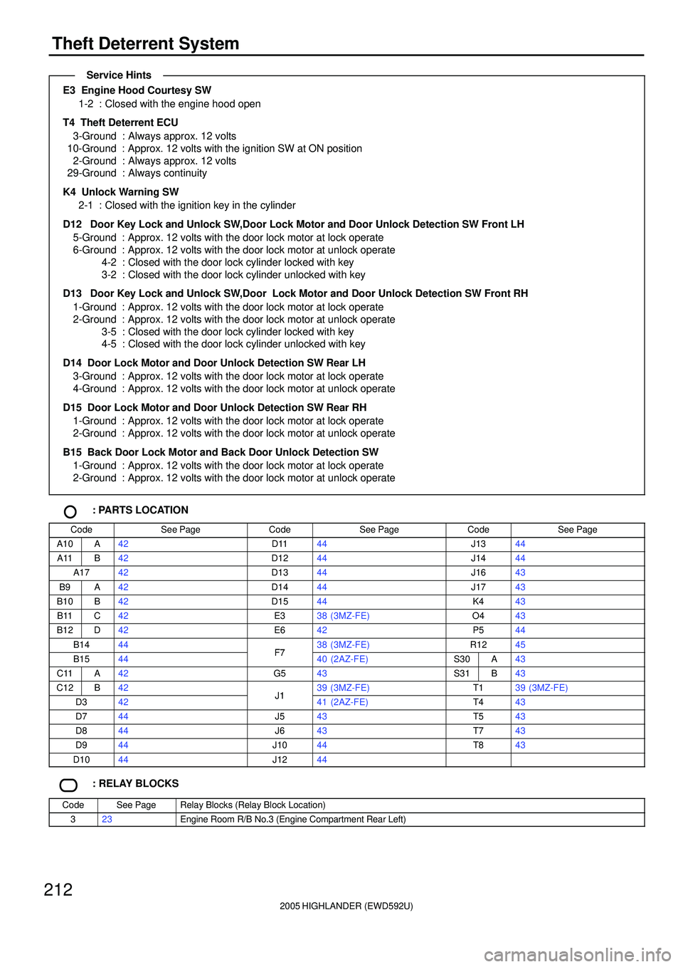
Theft Deterrent System
E3 Engine Hood Courtesy SW
1-2 : Closed with the engine hood open
T4 Theft Deterrent ECU
3-Ground : Always approx. 12 volts
10-Ground : Approx. 12 volts with the ignition SW at ON position
2-Ground : Always approx. 12 volts
29-Ground : Always continuity
K4 Unlock Warning SW
2-1 : Closed with the ignition key in the cylinder
D12 Door Key Lock and Unlock SW,Door Lock Motor and Door Unlock Detection SW Front LH
5-Ground : Approx. 12 volts with the door lock motor at lock operate
6-Ground : Approx. 12 volts with the door lock motor at unlock operate
4-2 : Closed with the door lock cylinder locked with key
3-2 : Closed with the door lock cylinder unlocked with key
D13 Door Key Lock and Unlock SW,Door Lock Motor and Door Unlock Detection SW Front RH
1-Ground : Approx. 12 volts with the door lock motor at lock operate
2-Ground : Approx. 12 volts with the door lock motor at unlock operate
3-5 : Closed with the door lock cylinder locked with key
4-5 : Closed with the door lock cylinder unlocked with key
D14 Door Lock Motor and Door Unlock Detection SW Rear LH
3-Ground : Approx. 12 volts with the door lock motor at lock operate
4-Ground : Approx. 12 volts with the door lock motor at unlock operate
D15 Door Lock Motor and Door Unlock Detection SW Rear RH
1-Ground : Approx. 12 volts with the door lock motor at lock operate
2-Ground : Approx. 12 volts with the door lock motor at unlock operate
B15 Back Door Lock Motor and Back Door Unlock Detection SW
1-Ground : Approx. 12 volts with the door lock motor at lock operate
2-Ground : Approx. 12 volts with the door lock motor at unlock operate
: PARTS LOCATION
CodeSee PageCodeSee PageCodeSee Page
A10A42D1144J1344
A11B42D1244J1444
A1742D1344J1643
B9A42D1444J1743
B10B42D1544K443
B11C42E338 (3MZ-FE)O443
B12D42E642P544
B1444F738 (3MZ-FE)R1245
B1544F740 (2AZ-FE)S30A43
C11A42G543S31B43
C12B42J139 (3MZ-FE)T139 (3MZ-FE)
D342J141 (2AZ-FE)T443
D744J543T543
D844J643T743
D944J1044T843
D1044J1244
: RELAY BLOCKS
CodeSee PageRelay Blocks (Relay Block Location)
323Engine Room R/B No.3 (Engine Compartment Rear Left)
Service Hints
Page 535 of 2572
2005 HIGHLANDER (EWD592U)
220
Front Wiper and Washer
C14
Wiper Relay
INT TIME Washer HIGH LOW
INT
OFF
3 2 1 4
5 M25A
WIPER
1B 2 20A
WASHER
1B 31E5
2 1
IK31
IA 11
16
7
8
17 2V
W- B
G
B
L
LGW
L- W
LG
B R
LG
B
L W- B
LG
W- B
F14
IC210
IC29
IC211
4C 5
4M 6
1E 4
1D 14
W- B
1B8
W- B MFrom Power Source System (
See Page 62)
Front Wiper and Washer SW
F 6
Combination SW
Front Wiper Motor
Front Washer
Motor
Page 536 of 2572
2005 HIGHLANDER (EWD592U)
221
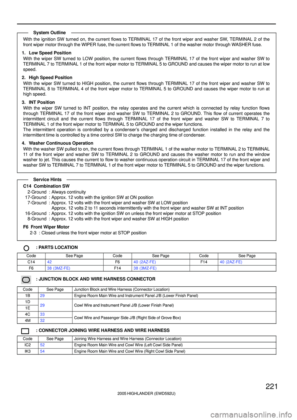
With the ignition SW turned on, the current flows to TERMINAL 17 of the front wiper and washer SW, TERMINAL 2 of the
front wiper motor through the WIPER fuse, the current flows to TERMINAL 1 of the washer motor through WASHER fuse.
1. Low Speed Position
With the wiper SW turned to LOW position, the current flows through TERMINAL 17 of the front wiper and washer SW to
TERMINAL 7 to TERMINAL 1 of the front wiper motor to TERMINAL 5 to GROUND and causes the wiper motor to run at low
speed.
2. High Speed Position
With the wiper SW turned to HIGH position, the current flows through TERMINAL 17 of the front wiper and washer SW to
TERMINAL 8 to TERMINAL 4 of the front wiper motor to TERMINAL 5 to GROUND and causes the wiper motor to run at
high speed.
3. INT Position
With the wiper SW turned to INT position, the relay operates and the current which is connected by relay function flows
through TERMINAL 17 of the front wiper and washer SW to TERMINAL 2 to GROUND. This flow of current operates the
intermittent circuit and the current flows through TERMINAL 17 of the front wiper and washer SW to TERMINAL 7 to
TERMINAL 1 of the front wiper motor to TERMINAL 5 to GROUND and the wiper functions.
The intermittent operation is controlled by a condenser's charged and discharged function installed in the relay and the
intermittent time is controlled by a time control SW to charge the charging time of condenser.
4. Washer Continuous Operation
With the washer SW pulled to on, the current flows through TERMINAL 1 of the washer motor to TERMINAL 2 to TERMINAL
11 of the front wiper and washer SW to TERMINAL 2 to GROUND and causes the washer motor to run and the window
washer to jet. This causes the current to flow to washer continuous operation circuit in TERMINAL 17 of the front wiper and
washer SW to TERMINAL 7 to TERMINAL 1 of the front wiper motor to TERMINAL 5 to GROUND and the wiper functions.
C14 Combination SW
2-Ground : Always continuity
17-Ground : Approx. 12 volts with the ignition SW at ON position
7-Ground : Approx. 12 volts with the front wiper and washer SW at LOW position
Approx. 12 volts 2 to 11 seconds intermittently with the front wiper and washer SW at INT position
16-Ground : Approx. 12 volts with the ignition SW on unless the front wiper motor at STOP position
8-Ground : Approx. 12 volts with the front wiper and washer SW at HIGH position
F6 Front Wiper Motor
2-3 : Closed unless the front wiper motor at STOP position
: PARTS LOCATION
CodeSee PageCodeSee PageCodeSee Page
C1442F640 (2AZ-FE)F1440 (2AZ-FE)
F638 (3MZ-FE)F1438 (3MZ-FE)
������ ���: JUNCTION BLOCK AND WIRE HARNESS CONNECTOR
CodeSee PageJunction Block and Wire Harness (Connector Location)
1B29Engine Room Main Wire and Instrument Panel J/B (Lower Finish Panel)
1D29Cowl Wire and Instrument Panel J/B (Lower Finish Panel)1E29Cowl Wire and Instrument Panel J/B (Lower Finish Panel)
4C33Cowl Wire and Passenger Side J/B (Right Side of Grove Box)4M32Cowl Wire and Passenger Side J/B (Right Side of Grove Box)
: CONNECTOR JOINING WIRE HARNESS AND WIRE HARNESS
CodeSee PageJoining Wire Harness and Wire Harness (Connector Location)
IC252Engine Room Main Wire and Cowl Wire (Left Cowl Side Panel)
IK354Engine Room Main Wire and Cowl Wire (Right Cowl Side Panel)
System Outline
Service Hints
Page 557 of 2572
2005 HIGHLANDER (EWD592U)
242
Horn
10A
HORN
62B 12E
6 11
H 8 H 7HORN
Relay
G- W
W- R P
G- W
IC2 4 51
32
I 1
P
10
HORN
B12 P
P P G- W G- W
From Power Source System (
See Page 62)
HornBody ECU Hor n LH Horn RH
Combination SW C16
Page 558 of 2572
2005 HIGHLANDER (EWD592U)
243
HORN Relay
5-3 : Closed with the horn SW on
: PARTS LOCATION
CodeSee PageCodeSee PageCodeSee Page
B1242H738 (3MZ-FE)H838 (3MZ-FE)
C1642H740 (2AZ-FE)H840 (2AZ-FE)
������ ���: JUNCTION BLOCK AND WIRE HARNESS CONNECTOR
CodeSee PageJunction Block and Wire Harness (Connector Location)
2B27Engine Room Main Wire and Engine Room J/B (Engine Compartment Left)2E27Engine Room Main Wire and Engine Room J/B (Engine Compartment Left)
: CONNECTOR JOINING WIRE HARNESS AND WIRE HARNESS
CodeSee PageJoining Wire Harness and Wire Harness (Connector Location)
IC252Engine Room Main Wire and Cowl Wire (Left Cowl Side Panel)
: SPLICE POINTS
CodeSee PageWire Harness with Splice PointsCodeSee PageWire Harness with Splice Points
I154Cowl Wire
Service Hints