Page 1703 of 2572
A80019
A81695A92146
Wire Harness Side
HT
+B
OX
E1
HT1B
OX1B
E8
ECM H10
Heated Oxygen Sensor
A90346
Reference (Bank 1 Sensor 2 System Drawing)
Heater
Sensor
Duty
Control ECM
From
Battery
EFI NO. 1
FuseEFI Relay
+B HT
EFI NO. 2
Fuse
MREL OX1B HT1B Heated Oxygen Sensor
OB1- OX E1
- DIAGNOSTICSSFI SYSTEM (2AZ-FE)
05-129
319 Author�: Date�:
2005 HIGHLANDER REPAIR MANUAL (RM1144U)
9 CHECK WIRE HARNESS
(a) Check the wire harness between the ECM and heated ox-
ygen sensor.
(1) Disconnect the H10 heated oxygen sensor connec-
tor.
(2) Disconnect the E8 ECM connector.
(3) Measure the resistance of the wire harness side
connectors.
Standard:
Tester ConnectionSpecified Condition
H10-2 (HT) - E8-21 (HT1B)
H10-4 (OX) - E8-29 (OX1B)Below 1 W
H10-2 (HT) or E8-21 (HT1B) - Body ground
H10-4 (OX) or E8-29 (OX1B) -Body ground10 kW or higher
NG REPAIR OR REPLACE HARNESS AND
CONNECTOR
OK
Page 1716 of 2572
A90346
A/F Sensor
Heater
Sensor
A1A+ HA1A
Duty
Control ECM
From
Battery
EFI NO. 1
Fuse
A1A-
MREL EFI Relay
+B
AF-
AF+ HT
EFI NO. 2
Fuse Reference (Bank 1 Sensor 1 System Drawing)
12
34
Y
A76787
A81695A85512
Wire Harness Side
A6
A/F Sensor
+B
AF- HT
AF+
E8
ECM
A1A+
A1A-
HA1A
05-142
- DIAGNOSTICSSFI SYSTEM (2AZ-FE)
332 Author�: Date�:
2005 HIGHLANDER REPAIR MANUAL (RM1144U)
12 CHECK WIRE HARNESS (A/F SENSOR - ECM)
(a) Disconnect the A6 A/F sensor connector.
(b) Disconnect the E8 ECM connector.
(c) Measure the resistance of the wire harness side connec-
tors.
Standard:
Tester ConnectionSpecified Condition
A6-3 (AF+) - E8-23 (A1A+)
A6-4 (AF-) - E8-31 (A1A-)
A6-1 (HT) - E8-5 (HA1A)
Below 1 W
A6-3 (AF+) or E8-23 (A1A+) - Body ground
A6-4 (AF-) or E8-31 (A1A-) - Body ground
A6-1 (HT) or E8-5 (HA1A) - Body ground
10 kW or higher
NG REPAIR OR REPLACE HARNESS AND
CONNECTOR
OK
13 REPLACE AIR FUEL RATIO SENSOR
GO
Page 1717 of 2572
 38 to 75 mph
Idling
IG SW OFF
3 to 5 minutes
Time 2 minutes
(a), (b), (c)(e)
(d)
- DIAGNOSTICSSFI SYSTEM (2AZ-FE)
05-143
333 Author�: Date�:
2005 HIGHLANDER REPAI")
A79199
Vehicle Speed
(60 to 120 km/h) 38 to 75 mph
Idling
IG SW OFF
3 to 5 minutes
Time 2 minutes
(a), (b), (c)(e)
(d)
- DIAGNOSTICSSFI SYSTEM (2AZ-FE)
05-143
333 Author�: Date�:
2005 HIGHLANDER REPAIR MANUAL (RM1144U)
14 PERFORM CONFIRMATION DRIVING PATTERN
(a) Clear the DTCs.
(1) Disconnect the battery cable or remove the EFI NO. 1 and ETCS fuses for 60 seconds or more.
(b) Connect the hand-held tester to the DLC3.
(c) Switch the hand-held tester from the normal mode to the check mode (see page 05-40).
(d) Start the engine and warm it up with all the accessory switches OFF.
(e) Drive the vehicle at 38 to 75 mph (60 to 120 km/h) and engine speed at 1,400 to 3,200 rpm for 3 to
5 minutes.
HINT:
If a malfunction exists, the MIL will be illuminated during step (e).
NOTICE:
If the conditions in this test are not strictly followed, detecting a malfunction may be difficult. If you
do not have a hand-held tester, turn the ignition switch OFF after performing steps (d) to (e), and then
do step (e) again.
GO
15 READ OUTPUT DTC (DTC P0171, P0172 ARE OUTPUT AGAIN)
(a) Read the DTC using the hand-held tester or the OBD II scan tool.
Result:
Display (DTC Output)Proceed to
DTC P0171, P0172 are not output againA
DTC P0171, P0172 are output againB
B REPLACE ECM (See page 10-9) AND PERFORM
CONFIRMATION DRIVING PATTERN
(Refer to step 14)
A
Page 1730 of 2572
A85366
A81699A85514
Wire Harness Side
I8
I9
I10
I11
Injector
#3 (+)#2 (+)
#4(+)#1 (+) E7
ECM
A90345
IG2 Fuse Instrument
Panel J/B
Assy
05-156
- DIAGNOSTICSSFI SYSTEM (2AZ-FE)
346 Author�: Date�:
2005 HIGHLANDER REPAIR MANUAL (RM1144U)
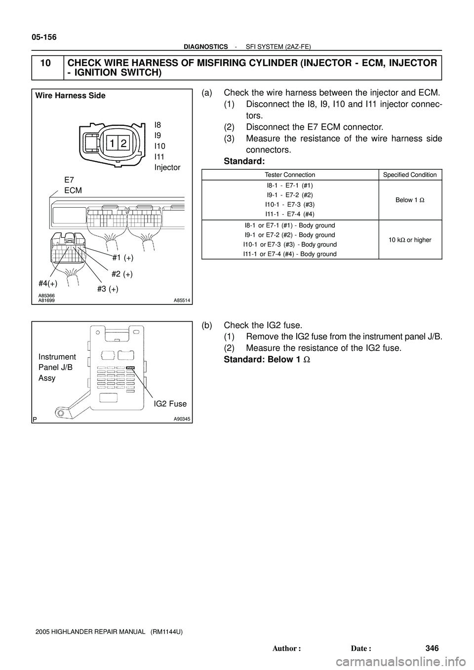
10 CHECK WIRE HARNESS OF MISFIRING CYLINDER (INJECTOR - ECM, INJECTOR
- IGNITION SWITCH)
(a) Check the wire harness between the injector and ECM.
(1) Disconnect the I8, I9, I10 and I11 injector connec-
tors.
(2) Disconnect the E7 ECM connector.
(3) Measure the resistance of the wire harness side
connectors.
Standard:
Tester ConnectionSpecified Condition
I8-1 - E7-1 (#1)
I9-1 - E7-2 (#2)
I10-1 - E7-3 (#3)
I11-1 - E7-4 (#4)
Below 1 W
I8-1 or E7-1 (#1) - Body ground
I9-1 or E7-2 (#2) - Body ground
I10-1 or E7-3 (#3) -Body ground
I11-1 or E7-4 (#4) - Body ground
10 kW or higher
(b) Check the IG2 fuse.
(1) Remove the IG2 fuse from the instrument panel J/B.
(2) Measure the resistance of the IG2 fuse.
Standard: Below 1 W
Page 1756 of 2572

A54393
Wire Harness Side
I2
I3
I4
I5
Ignition Coil
A90345
IG2 fuse Instrument
Panel J/B
Assy
Y
A54393
A61075
1234
5678
A85536
I2
I3
I4
I5
Ignition Coil
IG2
I15
Ignition Switch Wire Harness Side
05-182
- DIAGNOSTICSSFI SYSTEM (2AZ-FE)
372 Author�: Date�:
2005 HIGHLANDER REPAIR MANUAL (RM1144U)
6 CHECK IGNITION COIL ASSY (POWER SOURCE)
(a) Disconnect the I2, I3, I4 and I5 ignition coil connectors.
(b) Turn the ignition switch ON.
(c) Measure the voltage of the wire harness side connector
and body ground.
Standard:
Tester ConnectionSpecified Condition
I2-1 - Body ground
I3-1 - Body ground
I4-1 - Body ground
I5-1 - Body ground
9 to 14 V
OK REPLACE IGNITION COIL ASSY
NG
7 CHECK WIRE HARNESS (IGNITION COIL ASSY - IGNITION SWITCH)
(a) Check the IG2 fuse.
(1) Remove the IG2 fuse from the instrument panel J/B
Assy.
(2) Measure the resistance of the IG2 fuse.
Standard: Below 1 W
(b) Disconnect the I2, I3, I4 and I5 ignition coil connectors.
(c) Disconnect the I15 ignition switch connector.
(d) Measure the resistance of the wire harness side connec-
tors.
Standard:
Tester ConnectionSpecified Condition
I2-1 - I15-6 (IG2)
I3-1 - I15-6 (IG2)
I4-1 - I15-6 (IG2)
I5-1 - I15-6 (IG2)
Below 1 W
I2-1 or I15-6 (IG2) - Body ground
I3-1 or I15-6 (IG2) - Body ground
I4-1 or I15-6 (IG2) - Body ground
I5-1 or I15-6 (IG2) - Body ground
10 kW or higher
NG REPAIR OR REPLACE HARNESS AND
CONNECTOR
OK
Page 1802 of 2572

05-219
409 Author�: Date�:
2005 HIGHLANDER REPAIR MANUAL (RM1144U)
DTC P0504 BRAKE SWITCH ºAº/ºBº CORRELATION
CIRCUIT DESCRIPTION
In addition to turning on the s")
- DIAGNOSTICSSFI SYSTEM (2AZ-FE)
05-219
409 Author�: Date�:
2005 HIGHLANDER REPAIR MANUAL (RM1144U)
DTC P0504 BRAKE SWITCH ºAº/ºBº CORRELATION
CIRCUIT DESCRIPTION
In addition to turning on the stop lamp, the stop lamp switch signals are used for a variety of engine, transmis-
sion, and suspension functions as well as being an input for diagnostic checks. It is important that the switch
operates properly, therefore this switch is designed with two complementary signal outputs: STP and ST1.
The ECM analyzes these signal outputs to detect malfunctions in the stop lamp switch.
HINT:
Normal condition is as shown in the table.
SignalBrake pedal releasedIn transitionBrake pedal depressed
STPOFFONON
ST1ONONOFF
DTC No.DTC Detection ConditionTrouble Area
P0504
Conditions (a), (b) and (c) continue for 0.5 seconds or more:
(a) Ignition switch ON
(b) Brake pedal released
(c) STP signal is OFF when the ST1 signal is OFF�Short in stop lamp switch signal circuit
�STOP fuse
�Stop lamp switch
�ECM
05EVK-05
Page 1816 of 2572
A90302
BATTECM
F7
FL Block Assy 32IEFI NO. 13
E5
11
BR
Battery1
E9
FL
MainE1 BR
A
A
BR
EE WEngine Room J/B
J7
J/C W
2B7
IK211
B-W
A90343EFI NO. 1 fuse Engine Room J/B
05-230
- DIAGNOSTICSSFI SYSTEM (2AZ-FE)
420 Author�: Date�:
2005 HIGHLANDER REPAIR MANUAL (RM1144U)
WIRING DIAGRAM
INSPECTION PROCEDURE
HINT:
Read freeze frame data using the hand-held tester or the OBD II scan tool. Freeze frame data records the
engine conditions when a malfunction is detected. When troubleshooting, freeze frame data can help deter-
mine if the vehicle was running or stopped, if the engine was warmed up or not, if the air-fuel ratio was lean
or rich, and other data from the time the malfunction occurred.
1 INSPECT FUSE (EFI NO. 1)
(a) Remove the EFI NO. 1 fuse from the engine room J/B.
(b) Measure the resistance of the EFI NO. 1 fuse.
Standard: Below 1 W
OK REPLACE FUSE
OK
Page 1818 of 2572

422 Author�: Date")
Y
A80025
A67445A92625
EFI NO. 1 Fuse
BATTE5
ECM
Engine Room J/B Wire Harness Side
A80025A92626
EFI NO. 1 FuseEngine Room J/B Wire Harness Side
05-232
- DIAGNOSTICSSFI SYSTEM (2AZ-FE)
422 Author�: Date�:
2005 HIGHLANDER REPAIR MANUAL (RM1144U)
3 CHECK WIRE HARNESS (ECM - EFI NO. 1 FUSE, EFI NO. 1 FUSE - BATTERY)
(a) Check the wire harness between the EFI NO. 1 fuse and
ECM.
(1) Remove the EFI NO. 1 fuse from the engine room
J/B.
(2) Disconnect the E5 ECM connector.
(3) Measure the resistance of the wire harness side
connectors.
Standard:
Tester ConnectionSpecified Condition
J/B EFI NO. 1 fuse terminal 2 - E5-3 (BATT)Below 1 W
J/B EFI NO. 1 fuse terminal 2 or E5-3 (BATT) - Body ground10 kW or higher
(b) Check the wire harness between the EFI NO. 1 fuse and
battery.
(1) Remove the EFI NO. 1 fuse from the engine room
J/B.
(2) Disconnect the battery positive cable.
(3) Measure the resistance of the wire harness side
connectors.
Standard:
Tester ConnectionSpecified Condition
Battery positive cable - J/B EFI NO. 1 fuse terminal 1Below 1 W
Battery positive cable or J/B EFI NO. 1 fuse terminal 1
- Body ground10 kW or higher
NG REPAIR OR REPLACE HARNESS AND
CONNECTOR
OK
CHECK AND REPLACE ENGINE ROOM J/B

Heater
Sensor
Duty
Control ECM
From
Battery
EFI NO. 1
F")

12
34
Y
A76787
A8")