Page 1563 of 2572
A90349
Battery FL
MainInstrument Panel J/B Assy
L-Y
1 11C1Passenger Side J/B
P
F7
FL Block Assy Y
Combination Meter IC1
E511 I15
Ignition
Switch
WECM
GR
10
AM2
W1G6
4M4
4E1
W
IG2
AM26
7
IL19
IL2 10 J6
J/C
E
E P
SB
L
C11SB
C12 13 4
MIL IGN
- DIAGNOSTICSSFI SYSTEM (2AZ-FE)
05-359
549 Author�: Date�:
2005 HIGHLANDER REPAIR MANUAL (RM1144U)
MIL CIRCUIT
CIRCUIT DESCRIPTION
The Malfunction Indicator Lamp (MIL) is used to indicate the ECM's detection of a vehicle malfunction.
The instrument panel IG2 fuse provides circuit power and the ECM provides the circuit ground that illumi-
nates the MIL.
MIL operations should be checked visually:
The MIL should be illuminated when the ignition is first turned ON. If the MIL is always ON or OFF, use the
hand-held tester or OBD II
scan tool and follow the procedures to determine the cause of problem.
WIRING DIAGRAM
05EW1-05
Page 1619 of 2572
12
34
A76787
A81695A86849
Wire Harness Side
A6
A/F Sensor
HT
+B
E8
ECM
HA1A
AF+AF-
A1A-A1A+
A90346
A/F Sensor
EFI Relay
Heater
Sensor
A1A+ HA1A
Duty
Control ECM
From
Battery
A1A-
MREL Reference
+B
AF-AF+ HT
EFI NO. 1
FuseEFI NO. 2
Fuse
05-308
- DIAGNOSTICSSFI SYSTEM (2AZ-FE)
498 Author�: Date�:
2005 HIGHLANDER REPAIR MANUAL (RM1144U)
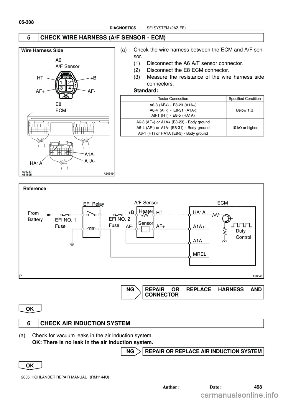
5 CHECK WIRE HARNESS (A/F SENSOR - ECM)
(a) Check the wire harness between the ECM and A/F sen-
sor.
(1) Disconnect the A6 A/F sensor connector.
(2) Disconnect the E8 ECM connector.
(3) Measure the resistance of the wire harness side
connectors.
Standard:
Tester ConnectionSpecified Condition
A6-3 (AF+) - E8-23 (A1A+)
A6-4 (AF-) - E8-31 (A1A-)
A6-1 (HT) - E8-5 (HA1A)
Below 1 W
A6-3 (AF+) or A1A+ (E8-23) - Body ground
A6-4 (AF-) or A1A- (E8-31) - Body ground
A6-1 (HT) or HA1A (E8-5) - Body ground
10 kW or higher
NG REPAIR OR REPLACE HARNESS AND
CONNECTOR
OK
6 CHECK AIR INDUCTION SYSTEM
(a) Check for vacuum leaks in the air induction system.
OK: There is no leak in the air induction system.
NG REPAIR OR REPLACE AIR INDUCTION SYSTEM
OK
Page 1631 of 2572
A67528A87357
OCV Signal Waveform
1 msec./Division5 V/
Division
GNDE9
ECM
OC1 +
OC1-
- DIAGNOSTICSSFI SYSTEM (2AZ-FE)
05-63
253 Author�: Date�:
2005 HIGHLANDER REPAIR MANUAL (RM1144U)
3 CHECK IF DTC OUTPUTS REOCCUR
(a) Erase the DTC(s) using one of the following methods: 1) use the hand-held tester, 2) disconnect the
battery cable for more than 60 seconds, or 3) remove the EFI NO. 1 and ETCS fuses for more than
60 seconds.
HINT:
After disconnecting the battery cable, perform the ºINITIALIZEº procedure (see page 05-893).
(b) Start and warm up the engine.
(c) Drive the vehicle for 10 minutes or more.
(d) Read output DTC using the hand-held tester.
OK: No DTC is output.
OK VVT SYSTEM OK*
HINT:
*: DTCs P0011 and P0012 are output when a foreign object in
the engine oil enters the system. These codes will stay even if
the system returns to normal after a short time. Foreign objects
are filtered out by the oil filter.
NG
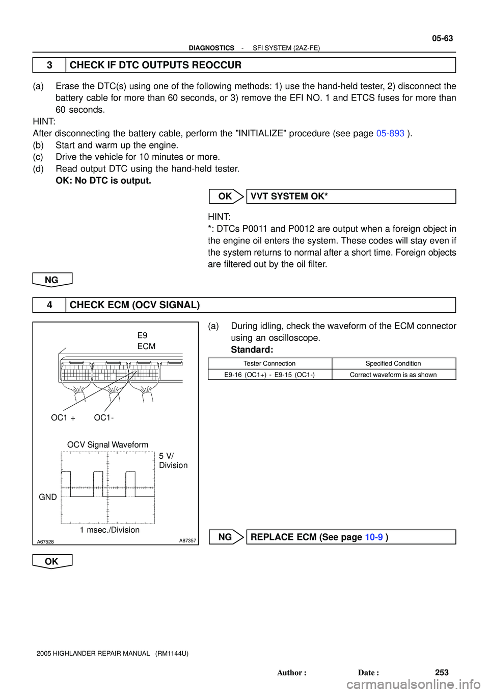
4 CHECK ECM (OCV SIGNAL)
(a) During idling, check the waveform of the ECM connector
using an oscilloscope.
Standard:
Tester ConnectionSpecified Condition
E9-16 (OC1+) - E9-15 (OC1-)Correct waveform is as shown
NG REPLACE ECM (See page 10-9)
OK
Page 1633 of 2572
A76968
(-) (+)
C2
OCV
- DIAGNOSTICSSFI SYSTEM (2AZ-FE)
05-65
255 Author�: Date�:
2005 HIGHLANDER REPAIR MANUAL (RM1144U)
11 CHECK IF DTC OUTPUTS REOCCUR
(a) Erase the DTC(s) using one of the following methods: 1) use the hand-held tester, 2) disconnect the
battery cable for more than 60 seconds, or 3) remove the EFI NO. 1 and ETCS fuses for more than
60 seconds.
HINT:
After disconnecting the battery cable, perform the ºINITIALIZEº procedure (see page 05-893).
(b) Start and warm up the engine.
(c) Drive the vehicle for 10 minutes or more.
(d) Read output DTC using the hand-held tester.
OK: No DTC is output.
OK VVT SYSTEM OK*
HINT:
*: DTCs P0011 and P0012 are output when a foreign object in
the engine oil enters the system. These codes will stay even if
the system returns to normal after a short time. Foreign objects
are filtered out by the oil filter.
NG
REPLACE ECM (See page 10-9)
OBD II scan tool (excluding hand-held tester):
1 CHECK VALVE TIMING (See page 14-68)
(a) Check for loose or jumped tooth of timing chain.
OK: The matchmarks of the crankshaft pulley and camshaft pulley are alined.
NG ADJUST VALVE TIMING (See page 14-68)
OK
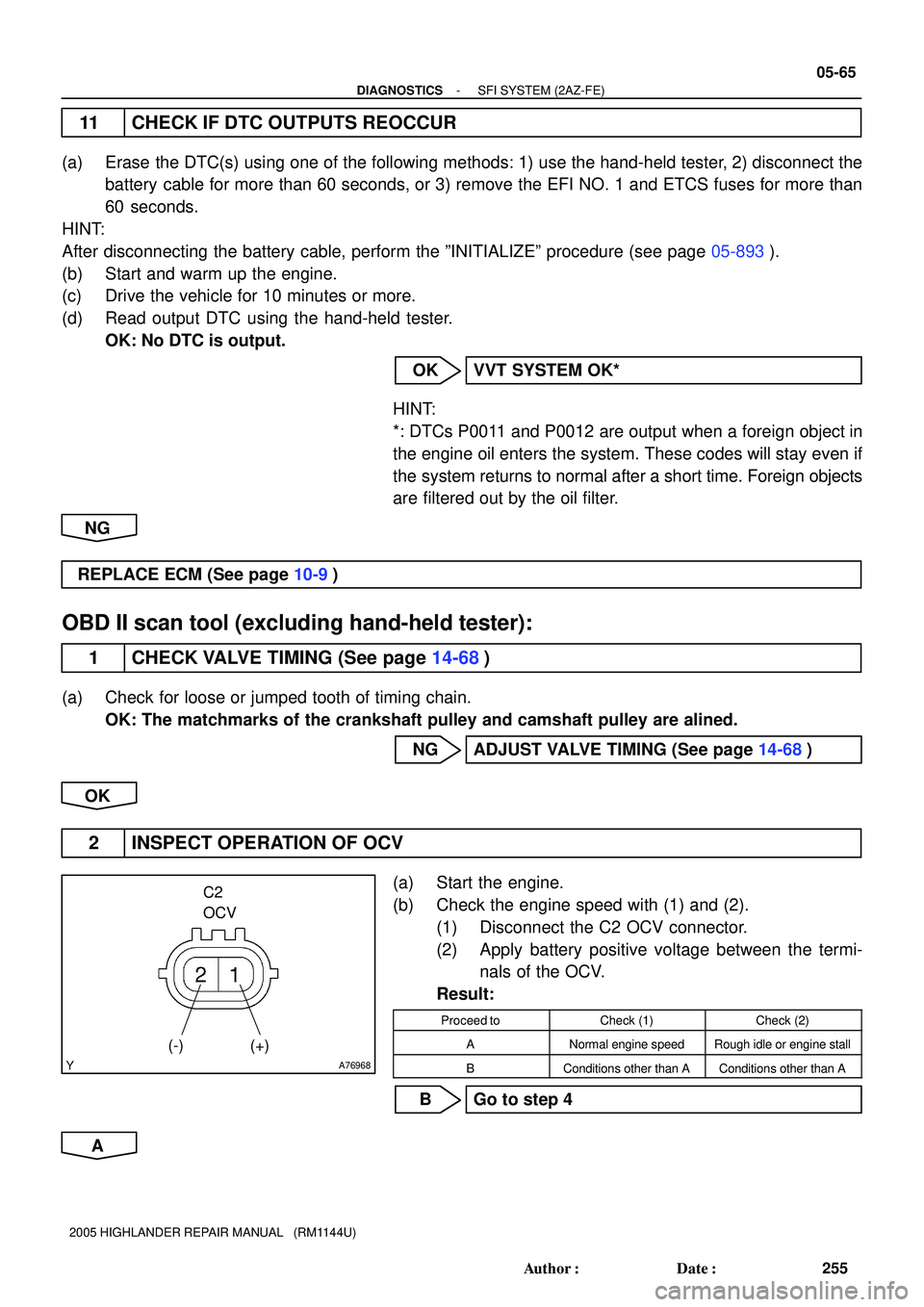
2 INSPECT OPERATION OF OCV
(a) Start the engine.
(b) Check the engine speed with (1) and (2).
(1) Disconnect the C2 OCV connector.
(2) Apply battery positive voltage between the termi-
nals of the OCV.
Result:
Proceed toCheck (1)Check (2)
ANormal engine speedRough idle or engine stall
BConditions other than AConditions other than A
B Go to step 4
A
Page 1634 of 2572
A67528A87357
OCV Signal Waveform
1 msec./Division5 V/
Division
GNDE9
ECM
OC1 +
OC1-
05-66
- DIAGNOSTICSSFI SYSTEM (2AZ-FE)
256 Author�: Date�:
2005 HIGHLANDER REPAIR MANUAL (RM1144U)
3 CHECK IF DTC OUTPUTS REOCCUR
(a) Erase the DTC(s) using one of the following methods: 1) use the hand-held tester, 2) disconnect the
battery cable for more than 60 seconds, or 3) remove the EFI NO. 1 and ETCS fuses for more than
60 seconds.
HINT:
After disconnecting the battery cable, perform the ºINITIALIZEº procedure (see page 05-893).
(b) Start and warm up the engine.
(c) Drive the vehicle for 10 minutes or more.
(d) Read output DTC using the hand-held tester.
OK: No DTC is output.
OK VVT SYSTEM OK*
HINT:
*: DTCs P0011 and P0012 are output when a foreign object in
the engine oil enters the system. These codes will stay even if
the system returns to normal after a short time. Foreign objects
are filtered out by the oil filter.
NG
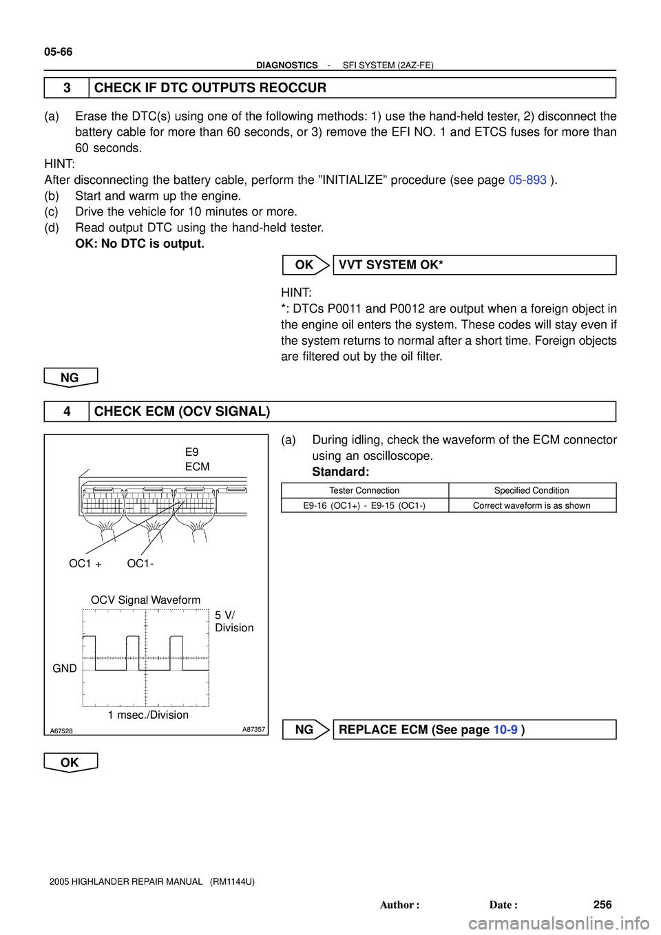
4 CHECK ECM (OCV SIGNAL)
(a) During idling, check the waveform of the ECM connector
using an oscilloscope.
Standard:
Tester ConnectionSpecified Condition
E9-16 (OC1+) - E9-15 (OC1-)Correct waveform is as shown
NG REPLACE ECM (See page 10-9)
OK
Page 1636 of 2572
05-68
- DIAGNOSTICSSFI SYSTEM (2AZ-FE)
258 Author�: Date�:
2005 HIGHLANDER REPAIR MANUAL (RM1144U)
11 CHECK IF DTC OUTPUTS REOCCUR
(a) Erase the DTC(s) using one of the following methods: 1) use the hand-held tester, 2) disconnect the
battery cable for more than 60 seconds, or 3) remove the EFI NO. 1 and ETCS fuses for more than
60 seconds.
HINT:
After disconnecting the battery cable, perform the ºINITIALIZEº procedure (see page 05-893).
(b) Start and warm up the engine.
(c) Drive the vehicle for 10 minutes or more.
(d) Read output DTC using the hand-held tester.
OK: No DTC is output.
OK VVT SYSTEM OK*
HINT:
*: DTCs P0011 and P0012 are output when a foreign object in
the engine oil enters the system. These codes will stay even if
the system returns to normal after a short time. Foreign objects
are filtered out by the oil filter.
NG
REPLACE ECM (See page 10-9)
Page 1639 of 2572
A90346
Reference
A/F Sensor
Heater
Sensor
A1A+ HA1A
Duty
Control ECM
From
Battery
EFI NO. 1
Fuse
A1A-
MREL EFI Relay
+B
AF-
AF+ HT
EFI NO. 2
Fuse
- DIAGNOSTICSSFI SYSTEM (2AZ-FE)
05-71
261 Author�: Date�:
2005 HIGHLANDER REPAIR MANUAL (RM1144U)
DTC P0031 OXYGEN (A/F) SENSOR HEATER CONTROL
CIRCUIT LOW (BANK 1 SENSOR 1)
DTC P0032 OXYGEN SENSOR HEATER CONTROL
CIRCUIT HIGH (BANK 1 SENSOR 1)
HINT:
Although the title (DTC description) says ºoxygen sensorº, this DTC is related to the ºA/F sensorº.
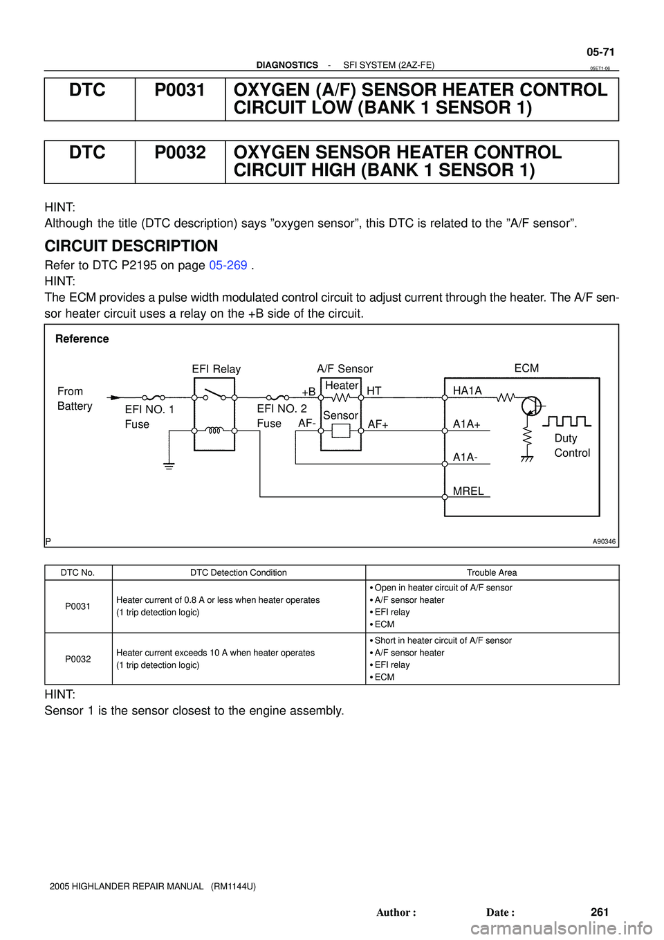
CIRCUIT DESCRIPTION
Refer to DTC P2195 on page 05-269.
HINT:
The ECM provides a pulse width modulated control circuit to adjust current through the heater. The A/F sen-
sor heater circuit uses a relay on the +B side of the circuit.
DTC No.DTC Detection ConditionTrouble Area
P0031Heater current of 0.8 A or less when heater operates
(1 trip detection logic)
�Open in heater circuit of A/F sensor
�A/F sensor heater
�EFI relay
�ECM
P0032Heater current exceeds 10 A when heater operates
(1 trip detection logic)
�Short in heater circuit of A/F sensor
�A/F sensor heater
�EFI relay
�ECM
HINT:
Sensor 1 is the sensor closest to the engine assembly.
05ET1-06
Page 1644 of 2572
A90346
Reference
Heater
Sensor
Duty
Control ECM
From
Battery
EFI NO. 1
FuseEFI Relay
+B HT
EFI NO. 2
Fuse
MREL OX1B HT1B Heated Oxygen Sensor
OB1- OX E1 05-76
- DIAGNOSTICSSFI SYSTEM (2AZ-FE)
266 Author�: Date�:
2005 HIGHLANDER REPAIR MANUAL (RM1144U)
DTC P0037 OXYGEN SENSOR HEATER CONTROL
CIRCUIT LOW (BANK 1 SENSOR 2)
DTC P0038 OXYGEN SENSOR HEATER CONTROL
CIRCUIT HIGH (BANK 1 SENSOR 2)
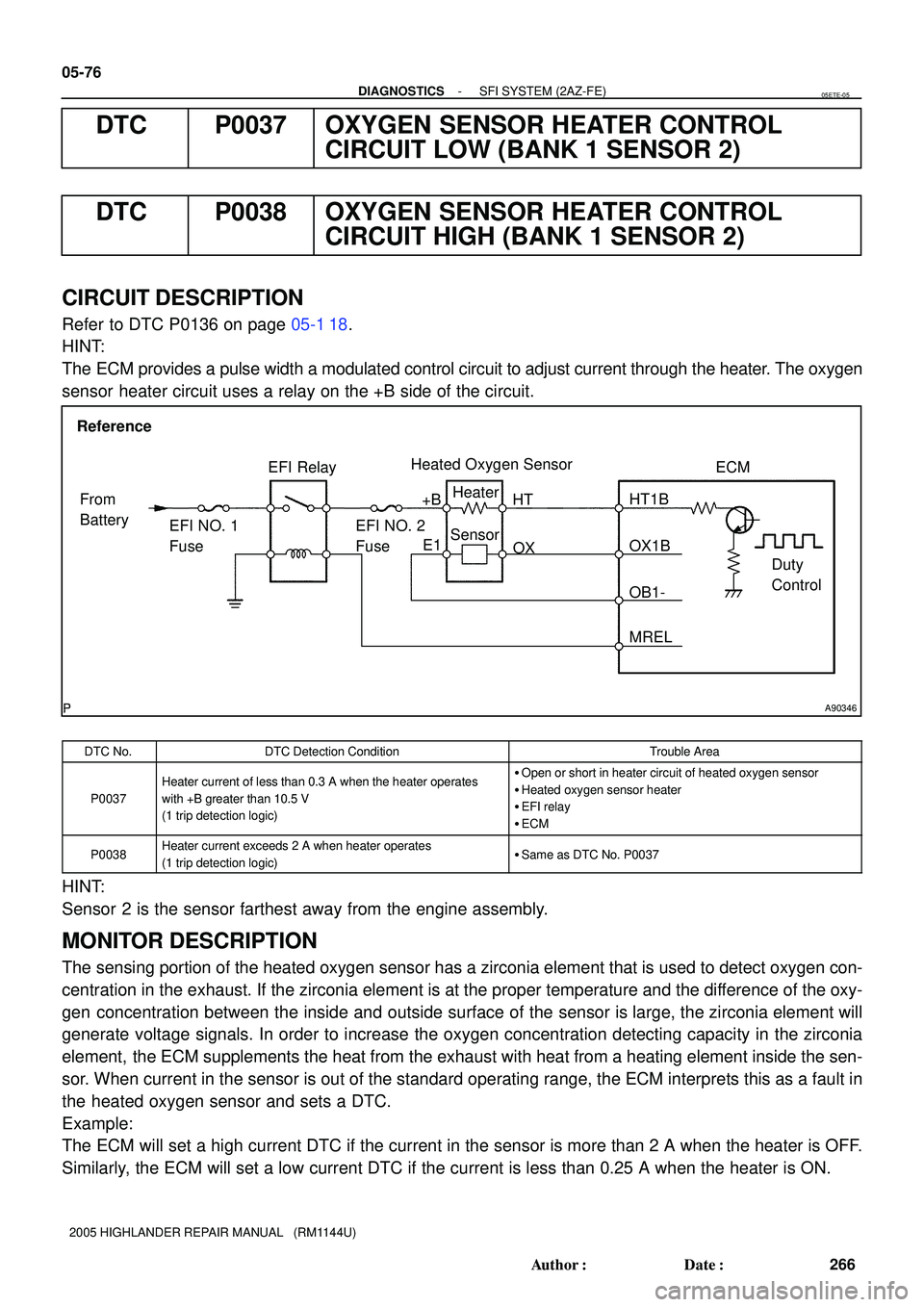
CIRCUIT DESCRIPTION
Refer to DTC P0136 on page 05-1 18.
HINT:
The ECM provides a pulse width a modulated control circuit to adjust current through the heater. The oxygen
sensor heater circuit uses a relay on the +B side of the circuit.
DTC No.DTC Detection ConditionTrouble Area
P0037
Heater current of less than 0.3 A when the heater operates
with +B greater than 10.5 V
(1 trip detection logic)�Open or short in heater circuit of heated oxygen sensor
�Heated oxygen sensor heater
�EFI relay
�ECM
P0038Heater current exceeds 2 A when heater operates
(1 trip detection logic)�Same as DTC No. P0037
HINT:
Sensor 2 is the sensor farthest away from the engine assembly.
MONITOR DESCRIPTION
The sensing portion of the heated oxygen sensor has a zirconia element that is used to detect oxygen con-
centration in the exhaust. If the zirconia element is at the proper temperature and the difference of the oxy-
gen concentration between the inside and outside surface of the sensor is large, the zirconia element will
generate voltage signals. In order to increase the oxygen concentration detecting capacity in the zirconia
element, the ECM supplements the heat from the exhaust with heat from a heating element inside the sen-
sor. When current in the sensor is out of the standard operating range, the ECM interprets this as a fault in
the heated oxygen sensor and sets a DTC.
Example:
The ECM will set a high current DTC if the current in the sensor is more than 2 A when the heater is OFF.
Similarly, the ECM will set a low current DTC if the current is less than 0.25 A when the heater is ON.
05ETE-05