Page 680 of 2572
'05 HIGHLANDER_U (L/O 0409)
378
2005 HIGHLANDER from Nov. '04 Prod. (OM48570U)
Tools:
�Funnel (only for adding coolant)
CHECKING BRAKE FLUID
Parts (if level is low):
�SAE J1703 or FMVSS No.116 DOT 3
brake fluid
Tools:
�Rag or paper towel
�Funnel (only for adding fluid)
CHECKING POWER STEERING FLUID
Parts (if level is low):
�Automatic transmission fluid
DEXRON�II or III
Tools:
�Rag or paper towel
�Funnel (only for adding fluid)
CHECKING BATTERY CONDITION
Tools:
�Warm water
�Baking soda
�Grease
�Conventional wrench
(for terminal clamp bolts)CHECKING AND REPLACING FUSES
Parts (if replacement is necessary):
�Fuse with same amperage rating as
original
ADDING WASHER FLUID
Parts:
�Water
�Washer fluid containing antifreeze
(for winter use)
Tools:
�Funnel
REPLACING LIGHT BULBS
Parts:
�Bulb with same number and wattage
rating as original (See charts in
Replacing light bulbsº on page 400 in
Section 7- 3.)
Tools:
�Screwdriver
Page 697 of 2572
'05 HIGHLANDER_U (L/O 0409)
395
2005 HIGHLANDER from Nov. '04 Prod. (OM48570U)
DO- IT- YOURSELF MAINTENANCE
Electrical components
Checking battery condition396 . . . . . . . . . . . . . . . . . . . . . . . . . . . . . . . . . .
Battery recharging precautions397 . . . . . . . . . . . . . . . . . . . . . . . . . . . . . . .
Checking and replacing fuses398 . . . . . . . . . . . . . . . . . . . . . . . . . . . . . . . .
Adding washer fluid399 . . . . . . . . . . . . . . . . . . . . . . . . . . . . . . . . . . . . . . . . .
Replacing light bulbs400 . . . . . . . . . . . . . . . . . . . . . . . . . . . . . . . . . . . . . . . .
SECTION 7- 3
Page 700 of 2572
'05 HIGHLANDER_U (L/O 0409)
398
2005 HIGHLANDER from Nov. '04 Prod. (OM48570U)
Good Blown
Ty p e A
Good Blown
Ty p e B
Good Blown
Ty p e C
If the headlights or other electrical
components do not work, check the
fuses. If any of the fuses are blown,
they must be replaced.
See Fuse locationsº on page 374 in Sec-
tion 7- 1 for locations of the fuses.
Turn the ignition switch and inoperative
component off. Pull the suspected fuse
straight out and check it.
Determine which fuse may be causing the
problem. The lid of the fuse box shows
the name of the circuit for each fuse. See
page 410 in Section 8 for the functions
controlled by each circuit.
Checking and replacing fuses
Page 701 of 2572
'05 HIGHLANDER_U (L/O 0409)
399
2005 HIGHLANDER from Nov. '04 Prod. (OM48570U)
Type A fuses can be pulled out by using
the pull- out tool. The location of the pull-
out tool is shown in the illustration.
If you are not sure whether the fuse has
blown, try replacing the suspected fuse
with one that you know is good.
If the fuse has blown, push a new fuse
into the clip.
Only install a fuse with the amperage rat-
ing designated on the fuse box lid.
If you do not have a spare fuse, in an
emergency you can pull out the FR DEFº
or CIGº fuse, which may be dispensable
for normal driving, and use it if its amper-
age rating is the same.
If you cannot use one of the same amper-
age, use one that is lower, but as close
to the rating as possible. If the amperage
is lower than that specified, the fuse
might blow out again but this does not
indicate anything wrong. Be sure to get
the correct fuse as soon as possible and
return the substitute to its original clip.
It is a good idea to purchase a set of
spare fuses and keep them in your ve-
hicle for emergencies.If the new fuse immediately blows out,
there is a problem with the electrical sys-
tem. Have your Toyota dealer correct it as
soon as possible.
You should normalize the moon roof if it
does not operate automatically or the jam
protection function does not operate cor-
rectly after replacing blown fuses. To
normalize the moon roof, see Electric
moon roofº on page 36 in Section 1- 2.
CAUTION
Never use a fuse with a higher am-
perage rating, or any other object, in
place of a fuse. This may cause ex-
tensive damage and possibly a fire.
If any washer does not work or the low
windshield washer fluid level warning
light comes on, the washer tank may be
empty. Add washer fluid.
You may use plain water as washer fluid.
However, in cold areas where tempera-
tures range below the freezing point, use
washer fluid containing antifreeze. This
product is available at your Toyota dealer
and most auto parts stores. Follow the
manufacturer 's directions for how much to
mix with water.
Adding washer fluid
Page 715 of 2572
'05 HIGHLANDER_U (L/O 0409)
273
2005 HIGHLANDER from Nov. '04 Prod. (OM48570U)
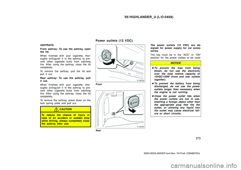
ASHTRAYS
Front ashtray: To use the ashtray, open
the lid.
When finished with your cigarette, thor-
oughly extinguish it in the ashtray to pre-
vent other cigarette butts from catching
fire. After using the ashtray, close the lid
completely.
To remove the ashtray, pull the lid and
pull it out.
Rear ashtray: To use the ashtray, pull
it out.
When finished with your cigarette, thor-
oughly extinguish it in the ashtray to pre-
vent other cigarette butts from catching
fire. After using the ashtray, close the lid
completely.
To remove the ashtray, press down on the
lock spring plate and pull out.
CAUTION
To reduce the chance of injury in
case of an accident or sudden stop
while driving, always completely close
the ashtray after use.
Front
Rear
The power outlets (12 VDC) are de-
signed for power supply for car acces-
sories.
The key must be in the ACCº or ONº
position for the power outlets to be used.
NOTICE
�To prevent the fuse from being
blown, do not use the electricity
over the total vehicle capacity of
12VDC/120W (front and rear outlets
together).
�To prevent the battery from being
discharged, do not use the power
outlets longer than necessary when
the engine is not running.
�Close the power outlet lids when
the power outlets are not in use.
Inserting a foreign object other than
the appropriate plug that fits the
outlet, or allowing any liquid into
the outlet may cause electrical fail-
ure or short circuits.
Power outlets (12 VDC)
Page 786 of 2572
05-804
- DIAGNOSTICSABS WITH EBD & BA & TRAC & VSC SYSTEM
994 Author�: Date�:
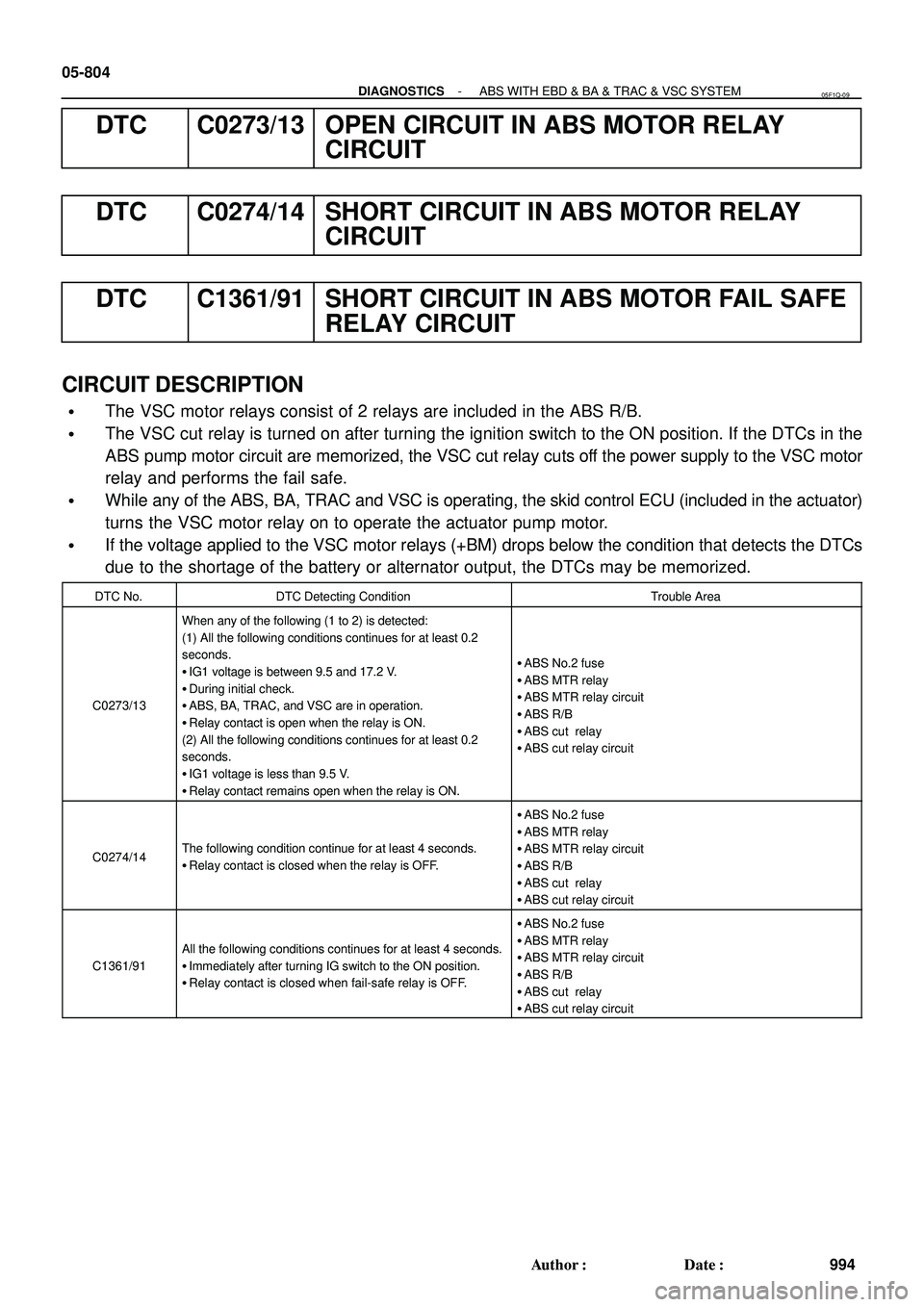
DTC C0273/13 OPEN CIRCUIT IN ABS MOTOR RELAY
CIRCUIT
DTC C0274/14 SHORT CIRCUIT IN ABS MOTOR RELAY
CIRCUIT
DTC C1361/91 SHORT CIRCUIT IN ABS MOTOR FAIL SAFE
RELAY CIRCUIT
CIRCUIT DESCRIPTION
�The VSC motor relays consist of 2 relays are included in the ABS R/B.
�The VSC cut relay is turned on after turning the ignition switch to the ON position. If the DTCs in the
ABS pump motor circuit are memorized, the VSC cut relay cuts off the power supply to the VSC motor
relay and performs the fail safe.
�While any of the ABS, BA, TRAC and VSC is operating, the skid control ECU (included in the actuator)
turns the VSC motor relay on to operate the actuator pump motor.
�If the voltage applied to the VSC motor relays (+BM) drops below the condition that detects the DTCs
due to the shortage of the battery or alternator output, the DTCs may be memorized.
DTC No.DTC Detecting ConditionTrouble Area
C0273/13
When any of the following (1 to 2) is detected:
(1) All the following conditions continues for at least 0.2
seconds.
�IG1 voltage is between 9.5 and 17.2 V.
�During initial check.
�ABS, BA, TRAC, and VSC are in operation.
�Relay contact is open when the relay is ON.
(2) All the following conditions continues for at least 0.2
seconds.
�IG1 voltage is less than 9.5 V.
�Relay contact remains open when the relay is ON.
�ABS No.2 fuse
�ABS MTR relay
�ABS MTR relay circuit
�ABS R/B
�ABS cut relay
�ABS cut relay circuit
C0274/14The following condition continue for at least 4 seconds.
�Relay contact is closed when the relay is OFF.
�ABS No.2 fuse
�ABS MTR relay
�ABS MTR relay circuit
�ABS R/B
�ABS cut relay
�ABS cut relay circuit
C1361/91
All the following conditions continues for at least 4 seconds.
�Immediately after turning IG switch to the ON position.
�Relay contact is closed when fail-safe relay is OFF.
�ABS No.2 fuse
�ABS MTR relay
�ABS MTR relay circuit
�ABS R/B
�ABS cut relay
�ABS cut relay circuit
05F1Q-09
Page 788 of 2572
F40458
ABS2 FL BLOCK
05-806
- DIAGNOSTICSABS WITH EBD & BA & TRAC & VSC SYSTEM
996 Author�: Date�:
INSPECTION PROCEDURE
HINT:
Start the inspection from step 1 when using the hand-held tester and start from step 2 when not using the
hand-held tester.
1 PERFORM ACTIVE TEST BY HAND-HELD TESTER(ABS MOTOR RELAY
OPERATION)
(a) Connect the hand-held tester to the DLC3.
(b) Start the engine.
(c) Select the ACTIVE TEST mode on the hand-held tester.
(d) Check the operation sound of the ABS motor individually when operating it with the hand-held tester.
ItemVehicle Condition / Test DetailsVehicle Condition / Test Details
ABS MOT RELAYABS motor relay / ON or OFFON : Motor relay ON
OK:
The operation sound of the ABS motor should be heard.
NG Go to step 2
OK
REPLACE ABS & TRACTION ACTUATOR ASSY (SEE PAGE 32-37)
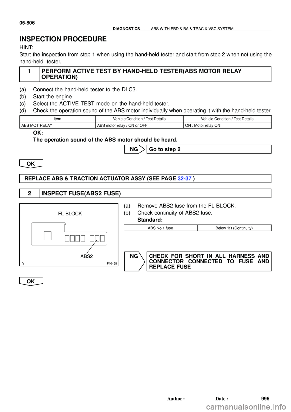
2 INSPECT FUSE(ABS2 FUSE)
(a) Remove ABS2 fuse from the FL BLOCK.
(b) Check continuity of ABS2 fuse.
Standard:
ABS No.1 fuseBelow 1W (Continuity)
NG CHECK FOR SHORT IN ALL HARNESS AND
CONNECTOR CONNECTED TO FUSE AND
REPLACE FUSE
OK
Page 791 of 2572
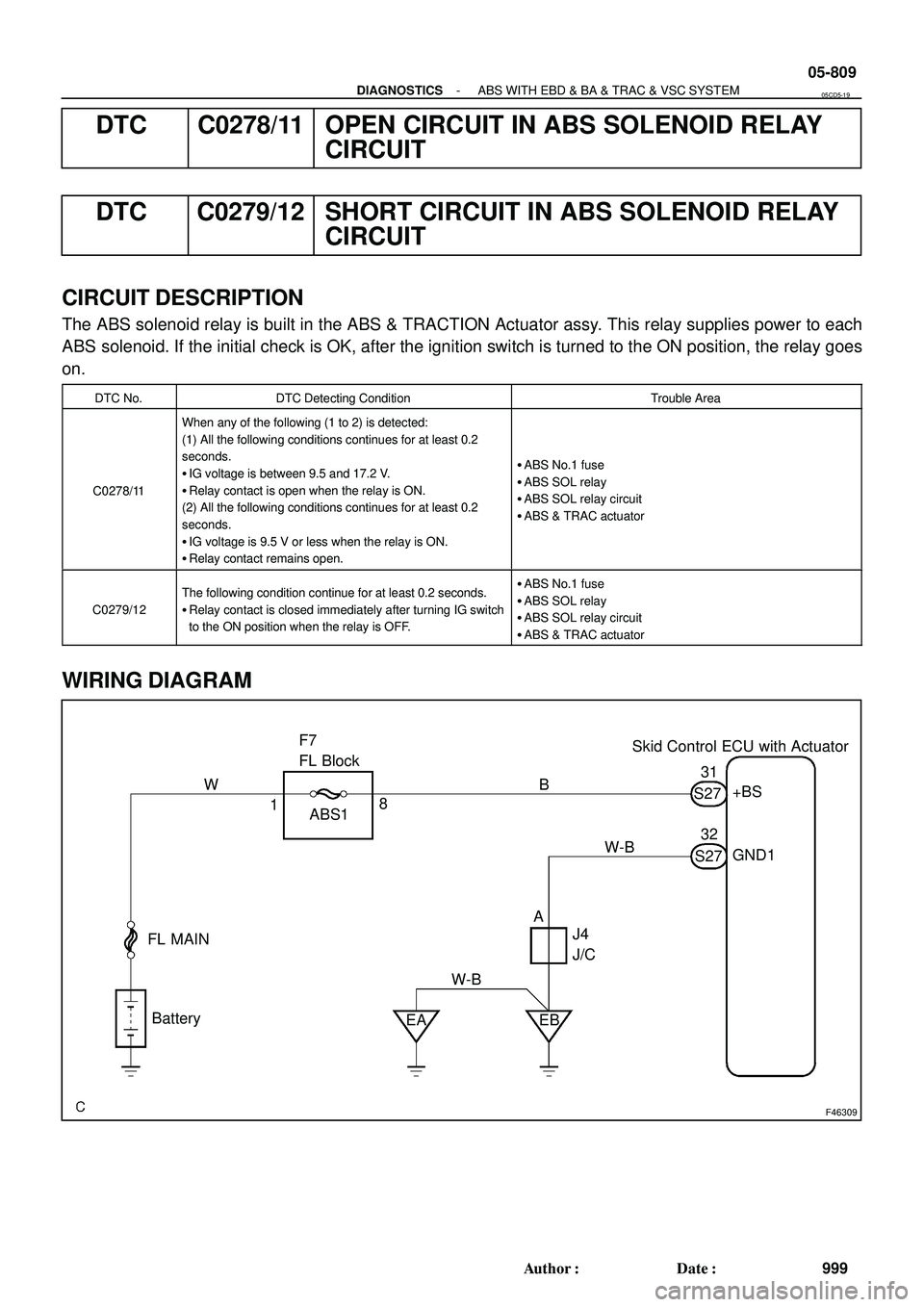
F46309
Skid Control ECU with Actuator F7
FL Block
FL MAIN
Battery
EA EB ABS1+BS
GND1
J4
J/C 1831
32
AB W
W-BS27
S27 W-B
- DIAGNOSTICSABS WITH EBD & BA & TRAC & VSC SYSTEM
05-809
999 Author�: Date�:
DTC C0278/11 OPEN CIRCUIT IN ABS SOLENOID RELAY
CIRCUIT
DTC C0279/12 SHORT CIRCUIT IN ABS SOLENOID RELAY
CIRCUIT
CIRCUIT DESCRIPTION
The ABS solenoid relay is built in the ABS & TRACTION Actuator assy. This relay supplies power to each
ABS solenoid. If the initial check is OK, after the ignition switch is turned to the ON position, the relay goes
on.
DTC No.DTC Detecting ConditionTrouble Area
C0278/11
When any of the following (1 to 2) is detected:
(1) All the following conditions continues for at least 0.2
seconds.
�IG voltage is between 9.5 and 17.2 V.
�Relay contact is open when the relay is ON.
(2) All the following conditions continues for at least 0.2
seconds.
�IG voltage is 9.5 V or less when the relay is ON.
�Relay contact remains open.
�ABS No.1 fuse
�ABS SOL relay
�ABS SOL relay circuit
�ABS & TRAC actuator
C0279/12
The following condition continue for at least 0.2 seconds.
�Relay contact is closed immediately after turning IG switch
to the ON position when the relay is OFF.�ABS No.1 fuse
�ABS SOL relay
�ABS SOL relay circuit
�ABS & TRAC actuator
WIRING DIAGRAM
05CD5-19