Page 1232 of 2572

(1) Disconnect the connectors of the master switch, body ECU and air condi")
B51827
P5
05-2054
- DIAGNOSTICSMULTIPLEX COMMUNICATION SYSTEM
2244 Author�: Date�:
2005 HIGHLANDER REPAIR MANUAL (RM1144U)
(1) Disconnect the connectors of the master switch, body ECU and air conditioner amplifier.
(2) Check the continuity between terminal P5-8 (MPX2) of the master switch vehicle's side connec-
tor and terminal B9-10 (MPX2) of the body ECU vehicle's side connector.
Standard: Continuity
(3) Check the continuity between terminal P5-7 (MPX1) of the master switch vehicle's side connec-
tor and terminal A17-22 (MPX2) of the airbag sensor assembly vehicle's side connector.
Standard: Continuity
NG REPAIR OR REPLACE HARNESS AND
CONNECTOR
OK
2 CHECK POWER WINDOW REGULATOR MASTER SWITCH ASSY
(a) Inspect the power window regulator master switch assy
(door ECU) (power source input).
(1) Disconnect the master switch connector.
(2) Check the voltage of each terminal of the master
switch vehicle's side connector.
Standard:
Symbols (Terminal No.)ConditionSpecified Condition
CPUB (P5-9) @ Body groundConstant10 - 14 V
BDR (P5-10) @ Body groundConstant10 - 14 V
NG REPAIR OR REPLACE FUSE OR WIRE
HARNESS AND CONNECTOR
OK
Page 1250 of 2572

(1) Disconnect the connectors of the air conditioner amplifier, master sw")
B51596
A10
- DIAGNOSTICSMULTIPLEX COMMUNICATION SYSTEM
05-2073
2263 Author�: Date�:
2005 HIGHLANDER REPAIR MANUAL (RM1144U)
(1) Disconnect the connectors of the air conditioner amplifier, master switch and meter assy.
(2) Inspect the continuity between terminal A10-9 (MPX-) of the air conditioner amplifier vehicle's
side connector and terminal C11-21 (MPX-) of the meter assy vehicle's side connector.
Standard: Continuity
(3) Inspect the continuity between terminal A11-2 (MPX+) of the air conditioner amplifier vehicle's
side connector and terminal P5-7 (MPX1) of the master switch.
Standard: Continuity
NG REPAIR OR REPLACE HARNESS AND
CONNECTOR
OK
2 CHECK AIRCONDITIONER AMPLIFIER ASSY
(a) Inspect the air conditioner amplifier assy (A/C ECU) (power source input).
(1) Disconnect the air conditioner amplifier connector A10.
(2) Inspect the voltage between terminal A10-12 (+B) of the vehicle's side connector and the body
ground.
Standard: 10 - 14 V
NG REPAIR OR REPLACE FUSE OR WIRE
HARNESS AND CONNECTOR
OK
Page 1255 of 2572

(1) Disconnect the connectors of the theft warning ECU, master switch and")
B50657
4T4
05-2078
- DIAGNOSTICSMULTIPLEX COMMUNICATION SYSTEM
2268 Author�: Date�:
2005 HIGHLANDER REPAIR MANUAL (RM1144U)
(1) Disconnect the connectors of the theft warning ECU, master switch and air conditioner amplifier.
(2) Check the continuity between terminal T4-31 (MPX1) of the theft warning ECU vehicle's side
connector and terminal C11-21 (MPX-) of the master switch vehicle's side connector.
(3) Check the continuity between terminal T4-31 (MPX1) of the theft warning ECU vehicle's side
connector and terminal A10-9 (MPX-) of the air conditioner amplifier vehicle's side connector.
Standard: Continuity
NG REPAIR OR REPLACE HARNESS AND
CONNECTOR
OK
2 CHECK THEFT WARNING ECU ASSY
(a) Inspect the theft warning ECU assy (theft deterrent ECU) (power source input).
(1) Disconnect the theft warning ECU connector.
(2) Check the voltage between terminal T4-2 (+B1) and T4-8 (+B2) of the theft warning ECU and
the body ground.
Standard: 10 - 14 V
NG REPAIR OR REPLACE FUSE OR WIRE
HARNESS AND CONNECTOR
OK
Page 1260 of 2572

(1) Disconnect the connectors of the sliding roof ECU, ECM and meter assy")
B51840
S20
05-2088
- DIAGNOSTICSMULTIPLEX COMMUNICATION SYSTEM
2278 Author�: Date�:
2005 HIGHLANDER REPAIR MANUAL (RM1144U)
(1) Disconnect the connectors of the sliding roof ECU, ECM and meter assy.
(2) Inspect the continuity between terminal S20-10 (MPX1) of the sliding roof ECU vehicle's side
connector and terminal E6-29 (MPX2) of the ECM vehicle's side connector.
Standard:
Symbols (Terminal No.)Specified Condition
MPX1 (S20-10) @ MPX2 (E6-29)
(equipped with 1MZ-FE)Continuity
MPX1 (S20-10) @ MPX2 (E6-29)
(equipped with 2AZ-FE)Continuity
(3) Inspect the continuity between terminal S20-10 (MPX1) of the sliding roof ECU vehicle's side
connector and terminal C12-9 (MPX+) of the meter assy vehicle's side connector.
Standard: Continuity
NG REPAIR OR REPLACE HARNESS AND
CONNECTOR
OK
2 CHECK SLIDING ROOF DRIVE GEAR SUB-ASSY
(a) Inspect the sliding roof drive gear sub-assy (sliding roof
ECU).
(1) Disconnect the sliding roof ECU connector.
(2) Inspect the voltage of each terminal of the vehicle's
side connector.
Standard:
Symbols (Terminal No.)ConditionSpecified Condition
B (S20-1) @ Body groundConstant10 - 14 V
NG REPAIR OR REPLACE FUSE OR WIRE
HARNESS AND CONNECTOR
OK
Page 1336 of 2572

B63408
Wire Harness Side
T4
Theft Warning ECU Assy
B63408
Wire Harness Side
T4
Theft Warning ECU Assy
- DIAGNOSTICSTHEFT DETERRENT SYSTEM
05-2027
2217 Author�: Date�:
2005 HIGHLANDER REPAIR MANUAL (RM1144U)
INSPECTION PROCEDURE
1 CHECK THEFT WARNING ECU ASSY (ECU-B)
(a) Remove the ECU-B fuse from the engine room J/B.
(b) Measure the resistance.
Standard: Below 1 W
OK PROCEED TO NEXT CIRCUIT INSPECTION
SHOWN IN PROBLEM SYMPTOMS TABLE
NG
2 CHECK WIRE HARNESS (POWER SOURCE)
(a) Disconnect the T4 ECU connector.
(b) Measure the voltage of the wire harness side connector.
Standard:
Tester ConnectionSpecified Condition
T4-2 (+B1) - T4-29 (E)10 to 14 V
NG REPAIR OR REPLACE HARNESS AND
CONNECTOR
OK
3 CHECK THEFT WARNING ECU ASSY (GROUND)
(a) Disconnect the T5 ECU connector.
(b) Measure the resistance between the wire harness side
connector and body ground.
Standard:
Tester ConnectionSpecified Condition
T4-2 (+B1) - Body groundBelow 1 W
T4-29 (E) - Body groundBelow 1 W
NG REPAIR OR REPLACE HARNESS AND
CONNECTOR
OK
PROCEED TO NEXT CIRCUIT INSPECTION
Page 1345 of 2572

05-41
231 Author�: Date�:
2005 HIGHLANDER REPAIR MANUAL (RM1144U)
2. CLEAR DTC (Using the")
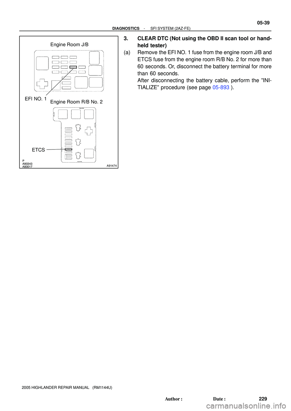
P
A90343
A80017
A91474
Engine Room J/B
ETCS EFI NO. 1
Engine Room R/B No. 2
- DIAGNOSTICSSFI SYSTEM (2AZ-FE)
05-41
231 Author�: Date�:
2005 HIGHLANDER REPAIR MANUAL (RM1144U)
2. CLEAR DTC (Using the OBD II scan tool or hand-held
tester)
(a) Connect the OBD II scan tool or the hand-held tester to
the DLC3.
(b) Turn the ignition switch ON.
(c) Erase DTCs and freeze frame data with the OBD II scan
tool (complying with SAE J1978) or the hand-held tester.
For the hand-held tester: 1) enter the following menus:
DIAGNOSIS / ENHANCED OBD II / DTC INFO / CLEAR
CODES; and 2) press YES. For the OBD II scan tool, see
its instruction manual.
3. CLEAR DTC (Not using the OBD II scan tool or hand-
held tester)
(a) Remove the EFI NO. 1 fuse from the engine room J/B and
ETCS fuse from the engine room R/B No. 2 for more than
60 seconds.
Or, disconnect the battery cable for more than 60 se-
conds. After disconnecting the battery terminal, perform
the ºINITIALIZEº procedure (see page 05-893).
Page 1406 of 2572
P
A90343
A80017
A91474
Engine Room J/B
ETCS EFI NO. 1
Engine Room R/B No. 2
- DIAGNOSTICSSFI SYSTEM (2AZ-FE)
05-39
229 Author�: Date�:
2005 HIGHLANDER REPAIR MANUAL (RM1144U)
3. CLEAR DTC (Not using the OBD II scan tool or hand-
held tester)
(a) Remove the EFI NO. 1 fuse from the engine room J/B and
ETCS fuse from the engine room R/B No. 2 for more than
60 seconds. Or, disconnect the battery terminal for more
than 60 seconds.
After disconnecting the battery cable, perform the ºINI-
TIALIZEº procedure (see page 05-893).
Page 1409 of 2572
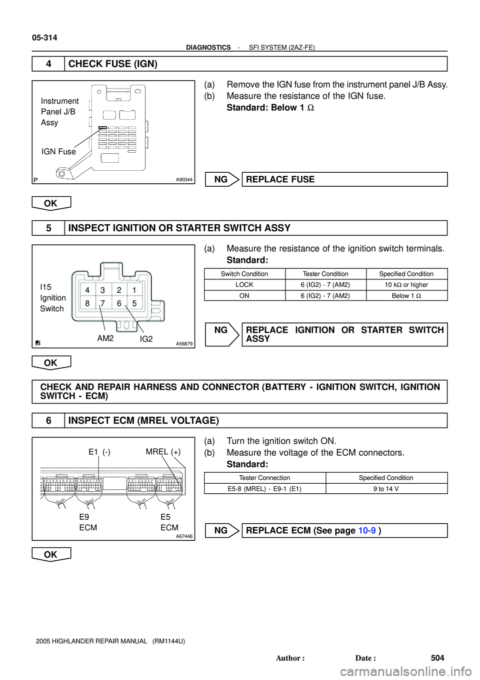
A90344
IGN Fuse Instrument
Panel J/B
Assy
1
5 6 2 3
7 8 4
A56879IG2 AM2
I15
Ignition
Switch
A67446
MREL (+)E1 (-)
E9
ECME5
ECM
05-314
- DIAGNOSTICSSFI SYSTEM (2AZ-FE)
504 Author�: Date�:
2005 HIGHLANDER REPAIR MANUAL (RM1144U)
4 CHECK FUSE (IGN)
(a) Remove the IGN fuse from the instrument panel J/B Assy.
(b) Measure the resistance of the IGN fuse.
Standard: Below 1 W
NG REPLACE FUSE
OK
5 INSPECT IGNITION OR STARTER SWITCH ASSY
(a) Measure the resistance of the ignition switch terminals.
Standard:
Switch ConditionTester ConditionSpecified Condition
LOCK6 (IG2) - 7 (AM2)10 kW or higher
ON6 (IG2) - 7 (AM2)Below 1 W
NG REPLACE IGNITION OR STARTER SWITCH
ASSY
OK
CHECK AND REPAIR HARNESS AND CONNECTOR (BATTERY - IGNITION SWITCH, IGNITION
SWITCH - ECM)
6 INSPECT ECM (MREL VOLTAGE)
(a) Turn the ignition switch ON.
(b) Measure the voltage of the ECM connectors.
Standard:
Tester ConnectionSpecified Condition
E5-8 (MREL) - E9-1 (E1)9 to 14 V
NG REPLACE ECM (See page 10-9)
OK