Page 792 of 2572
S27
05-810
- DIAGNOSTICSABS WITH EBD & BA & TRAC & VSC SYSTEM
1000 Author�: Date�:
INSPECTION PROCEDURE
1 INSPECT FUSE(AB")
F40458
ABS1 FL BLOCK
G24767
GND1
+BS Skid Control ECU
(harness side connector)S27
05-810
- DIAGNOSTICSABS WITH EBD & BA & TRAC & VSC SYSTEM
1000 Author�: Date�:
INSPECTION PROCEDURE
1 INSPECT FUSE(ABS1 FUSE)
(a) Remove ABS1 fuse from the FL BLOCK.
(b) Check continuity of ABS1 fuse.
Standard:
ABS No.2 fuseBelow 1 W (Continuity)
NG CHECK FOR SHORT IN ALL HARNESS AND
CONNECTOR CONNECTED TO FUSE AND
REPLACE FUSE
OK
2 INSPECT SKID CONTROL ECU CONNECTOR(+BS TERMINAL VOLTAGE)
(a) Disconnect the skid control ECU connector.
(b) Turn the ignition switch to the ON position.
(c) Measure the voltage according to the value(s) in the table
below.
Standard:
Tester ConnectionSpecified Condition
S27-31 (+BS) - S27-32 (GND1)10 to 14 V
NG Go to step 4
OK
3 RECONFIRM DTC
(a) Clear the DTCs (see page 05-765).
(b) Turn the ignition switch to the ON position.
(c) Are the same DTCs recorded?
NOTICE:
When replacing ABS & TRACTION ACTUATOR ASSY, perform zero point calibration
(see page 05-765).
NO PROCEED TO NEXT CIRCUIT INSPECTION
SHOWN IN PROBLEM SYMPTOMS TABLE
(SEE PAGE 05-786)
YES
REPLACE ABS & TRACTION ACTUATOR ASSY (SEE PAGE 32-37)
Page 810 of 2572
F40457
ECU-IG Instrument Panel J/B
05-828
- DIAGNOSTICSABS WITH EBD & BA & TRAC & VSC SYSTEM
1018 Author�: Date�:
INSPECTION PROCEDURE
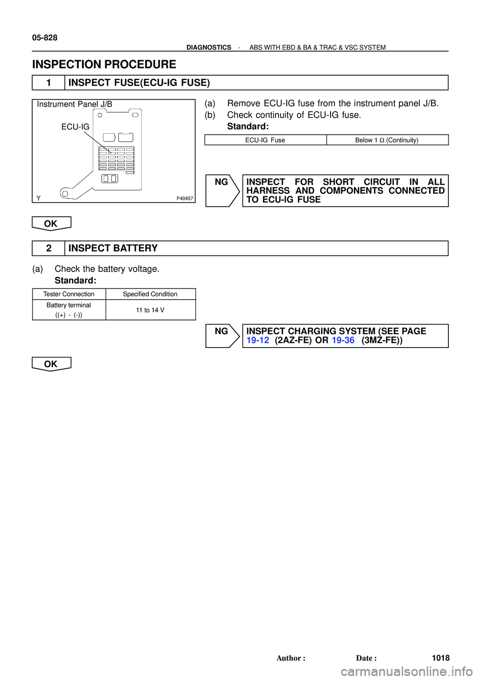
1 INSPECT FUSE(ECU-IG FUSE)
(a) Remove ECU-IG fuse from the instrument panel J/B.
(b) Check continuity of ECU-IG fuse.
Standard:
ECU-IG FuseBelow 1 W (Continuity)
NG INSPECT FOR SHORT CIRCUIT IN ALL
HARNESS AND COMPONENTS CONNECTED
TO ECU-IG FUSE
OK
2 INSPECT BATTERY
(a) Check the battery voltage.
Standard:
Tester ConnectionSpecified Condition
Battery terminal
((+) - (-))11 to 14 V
NG INSPECT CHARGING SYSTEM (SEE PAGE
19-12 (2AZ-FE) OR 19-36 (3MZ-FE))
OK
Page 834 of 2572

6 CHECK DOOR CONTROL RECEIVER
(")
B51930
Door Control
Receiver
W6 Wire Harness Side
- DIAGNOSTICSWIRELESS DOOR LOCK CONTROL SYSTEM
05-1973
2163 Author�: Date�:
2005 HIGHLANDER REPAIR MANUAL (RM1144U)
6 CHECK DOOR CONTROL RECEIVER
(a) Check the DOME fuse.
(b) Disconnect the W6 receiver connector.
(c) Check the voltage or continuity between the W6 receiver
wire harness side connector and body ground.
Standard:
Terminal No.Specified condition
5 - Body ground10 - 14 V
1 - Body groundContinuity
NG REPAIR OR REPLACE FUSE OR WIRE
HARNESS AND CONNECTOR
OK
REPLACE DOOR CONTROL RECEIVER
7 RE-REGISTER RECOGNITION CODE OF TRANSMITTER
(a) Check if it is possible to enter into the rewrite mode or the add mode for the recognition code registra-
tion, and if a recognition code can be registered, as well.
NG REPLACE MULTIPLEX NETWORK BODY ECU
OK
NORMAL (FUNCTION)
8 CONFIRM INPUT METHOD OF SELF-DIAGNOSTIC MODE
NG Go to step 3
OK
9 INSPECT UN-LOCK WARNING SWITCH ASSY (See page 05-1957)
NG REPLACE UN-LOCK WARNING SWITCH ASSY
OK
REPLACE MULTIPLEX NETWORK BODY ECU
Page 845 of 2572
A87847
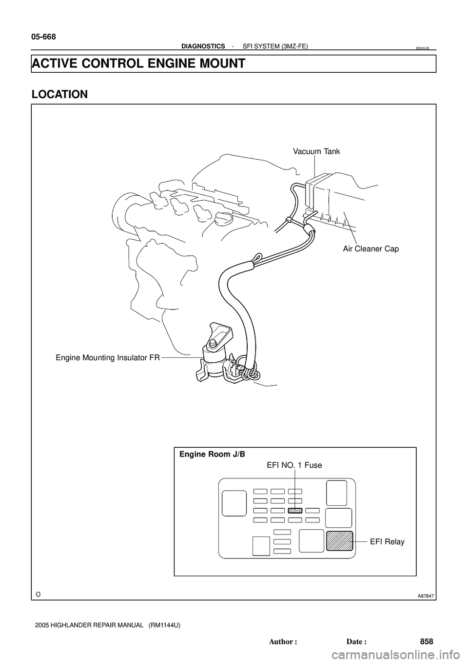
EFI Relay EFI NO. 1 Fuse Engine Room J/B
Vacuum Tank
Engine Mounting Insulator FR
Air Cleaner Cap
05-668
- DIAGNOSTICSSFI SYSTEM (3MZ-FE)
858 Author�: Date�:
2005 HIGHLANDER REPAIR MANUAL (RM1144U)
ACTIVE CONTROL ENGINE MOUNT
LOCATION
05EXI-05
Page 980 of 2572

(1) Disconnect the connectors of the meter assy, ECM and body EC")
A53766
E7
E8E9 E6E5
05-2068
- DIAGNOSTICSMULTIPLEX COMMUNICATION SYSTEM
2258 Author�: Date�:
2005 HIGHLANDER REPAIR MANUAL (RM1144U)
(1) Disconnect the connectors of the meter assy, ECM and body ECU.
(2) Inspect the continuity between terminals E6-18 (MPX1) of the ECM vehicle's side connector and
B10-6 (MPX1) of the body ECU vehicle's side connector.
Standard:
Symbols (Terminal No.)Specified Condition
MPX1 (E6-18) @ MPX1 (B10-6)
(equipped with 1MZ-FE)Continuity
MPX1 (E6-18) @ MPX1 (B10-6)
(equipped with 2AZ-FE)Continuity
(3) Inspect the continuity between terminals E6-29 (MPX2) of the ECM vehicle's side connector and
C12-9 (MPX+) of the meter assy vehicle's side connector.
Standard:
Symbols (Terminal No.)Specified Condition
MPX2 (E6-29) @ MPX+ (C12-9)
(equipped with 1MZ-FE)Continuity
MPX2 (E6-29) @ MPX+ (C12-9)
(equipped with 2AZ-FE)Continuity
NG REPAIR OR REPLACE HARNESS AND
CONNECTOR
OK
2 CHECK ECM
(a) Inspect the ECM (power source input).
NOTICE:
Do not disconnect the ECM connector. The inspection should be started from the backside of the
connector.
Standard:
Symbols (Terminal No.)In/OutputConditionSpecified Condition
BATT (E5-3) @ Body groundInputConstant9 - 14 V
+B (E5-1) @ Body groundInputEngine stopped, ignition switch ON9 - 14 V
+B2 (E5-2) @ Body groundInputEngine stopped, ignition switch ON9 - 14 V
NG REPAIR OR REPLACE FUSE OR WIRE
HARNESS AND CONNECTOR
OK
Page 991 of 2572

(1) Disconnect the connectors of the meter assy, ECM and air conditioner")
B51838
C11
- DIAGNOSTICSMULTIPLEX COMMUNICATION SYSTEM
05-2083
2273 Author�: Date�:
2005 HIGHLANDER REPAIR MANUAL (RM1144U)
(1) Disconnect the connectors of the meter assy, ECM and air conditioner amplifier.
(2) Inspect the continuity between terminal C12-9 (MPX+) of the meter assy vehicle's side connec-
tor and terminal E6-29 (MPX2) of the ECM vehicle's side connector.
Standard:
Symbols (Terminal No.)Specified Condition
MPX+ (C12-9) @ MPX2 (E6-29)
(equipped with 1MZ-FE)Continuity
MPX+ (C12-9) @ MPX2 (E6-29)
(equipped with 2AZ-FE)Continuity
(3) Inspect the continuity between terminal C11-21 (MPX-) of the meter assy vehicle's side connec-
tor and terminal A10-9 (MPX-) of the air conditioner amplifier vehicle's side connector.
Standard: Continuity
NG REPAIR OR REPLACE HARNESS AND
CONNECTOR
OK
2 CHECK COMBINATION METER ASSY
(a) Inspect the combination meter assy (meter ECU) (power source input).
(1) Disconnect the meter assy connector C11.
(2) Inspect the voltage of each terminal of the vehicle's side connector.
Standard:
Symbols (Terminal No.)ConditionSpecified Condition
B (C11-2) @ Body groundConstant10 - 14 V
B1 (C11-12) @ Body groundConstant10 - 14 V
HINT:
If the value is not as specified, there may be a malfunction in the vehicle's side connector.
NG REPAIR OR REPLACE FUSE OR WIRE
HARNESS AND CONNECTOR
OK
Page 1083 of 2572

DTC B1795 OCCUPANT CLASSIFICATION ECU
MALFUNCTION
CIRCUIT DESCRIPTION
DTC B1795 is rec")
05-1510
- DIAGNOSTICSSUPPLEMENTAL RESTRAINT SYSTEM
1700 Author�: Date�:
2005 HIGHLANDER REPAIR MANUAL (RM1144U)
DTC B1795 OCCUPANT CLASSIFICATION ECU
MALFUNCTION
CIRCUIT DESCRIPTION
DTC B1795 is recorded when a malfunction is detected in the occupant classification ECU.
Troubleshoot DTC B1771 first when the DTC B1771 and B1795 are output simultaneously.
DTC No.DTC Detecting ConditionTrouble Area
B1795
�Occupant classification ECU circuit malfunction
�Occupant classification ECU malfunction
�When the occupant classification ECU receives a short to
ground signal in the passenger side buckle switch circuit
for 2 seconds.
�The occupant classification ECU receives the ignition
switch LOCK to ON signal 50 times in a row when a mal-
function occurs in the power circuit for the occupant clas-
sification ECU (LOCK to ON to LOCK should be counted
as once).
�Occupant classification ECU
�Front seat wire RH
�ECU-B Fuse
�Front seat inner belt assy RH (Buckle switch RH)
HINT:
�When DTC B1150/23 is detected as a result of troubleshooting for the supplemental restraint system,
perform troubleshooting for DTC B1795 of the occupant classification sensor.
�Use the hand-held tester to check the DTC of the occupant classification ECU, otherwise the DTC
cannot be read.
05IX0-03
Page 1084 of 2572

INSPECTION PROCEDURE
1 CHECK DTC
(a) Turn the ignition switch to the")
H43112
O6
+BGND
- DIAGNOSTICSSUPPLEMENTAL RESTRAINT SYSTEM
05-151 1
1701 Author�: Date�:
2005 HIGHLANDER REPAIR MANUAL (RM1144U)
INSPECTION PROCEDURE
1 CHECK DTC
(a) Turn the ignition switch to the ON position, and wait for at least 10 seconds.
(b) Using the hand-held tester, check the DTCs (see page 05-1215).
Result:
A: DTC B1771 and B1795 are output.
B: DTC B1795 is output.
HINT:
Codes other than code B1771 and B1795 may be output at this time, but they are not related to this check.
A GO TO DTC B1771 (SEE PAGE 05-1446)
B
2 CHECK FUSE
(a) Check the ECU-B fuse.
Standard: Below 1 W
NG REPLACE FUSE
OK
3 CHECK WIRE HARNESS(SOURCE VOLTAGE)
(a) Turn the ignition switch to the LOCK position.
(b) Disconnect the negative (-) terminal cable from the bat-
tery, and wait for at least 90 seconds.
(c) Disconnect the ºO6º connector from the occupant classifi-
cation ECU.
(d) Connect the negative (-) terminal cable to the battery.
(e) Turn the ignition switch to the ON position.
(f) Measure the voltage and resistance according to the val-
ue(s) in the table below.
Standard:
Tester connectionConditionSpecified condition
O6-1 (+B) - Body groundIgnition switch ON10 to 14 V
O6-3 (GND) -
Body groundAlwaysBelow 1 W
NG REPAIR OR REPLACE WIRE HARNESS OR
BATTERY
OK
CHECK USE SIMULATION METHOD TO CHECK (SEE PAGE 05-1207)