Page 2166 of 2572

9
B
The ºCurrent Flow Chartº section, describes which parts each power source (fuses, fusible links, and circuit breakers)
transmits current to. In the Power Source circuit")
2005 HIGHLANDER (EWD592U)
9
B
The ºCurrent Flow Chartº section, describes which parts each power source (fuses, fusible links, and circuit breakers)
transmits current to. In the Power Source circuit diagram, the conditions when battery power is supplied to each system
are explained. Since all System Circuit diagrams start from the power source, the power source system must be fully
understood.
ACC
S 26
652
22
Battery30A AM2
StarterShort Pin
100A ALT Fusible Link Block
60A ABS10A ECU-B
7.5A DOME
15A EFI
10A HAZARD
20A RADIO NO.1
10A HORN
20A
10AFusePage
214
230
11 2
122 194
187
180
166
210 ABS
Cigarette Lighter
Combination Meter
Key Reminder and Seat Belt Warning
Light Auto Turn Off
Theft Deterrent and Door Lock ControlABS and Traction Control
Cruise Control
Electronically Controlled Transmission
Multiplex Communication System STOPSystem
DOMEHeadlight
Interior Light
3 EA2 1 EA1E 6
E 7
E 7
2
2
2
2 2
2 2
2 INJECTION Relay
STARTER Relay B
B
B B-O
1
1 2
23
4
3
4W-B W-B
B-W
B-W E 7
E 7B
BW1.25B FL MAIN
50A MAIN
7.5A AM2
15A HAZ-RADIO 2
22
2
2W
WEB1
EB17
6
W-RI 2 I 2 I 2
WW
W W W
1 1
1 140A DOOR LOCK CB
7.5A DOME 1W-L
R 1
1
2
431
1 1
1
111 G
G
W-R 15A TAIL
20A DEFOG
B-Y 84
32Ignition SW I 8
B-Y
11P-L Battery
15A RAD CIG2
TAIL
Relay
Power Source J POWER SOURCE (Current Flow Chart)
Engine Room R/B (See Page 20)
2
W W
B B B B B
W-R
WW W
G-WAM2
AM1 IG2
IG1W
W
The chart below shows the route by which current flows from the battery to each electrical source
(Fusible Link, Circuit Breaker, Fuse, etc.) and other parts.
*The system shown here is an EXAMPLE ONLY. It is different to the actual circuit shown in the SYSTEM CIRCUITS SECTION.
Page 2196 of 2572
Abbreviations Meaning
H-FUSEHigh Current Fuse
HIHigh
HIDHigh Intensity Discharge (Head Lamp)
HSGHousing
HTHard Top")
- INTRODUCTIONTERMS
01-43
43 Author�: Date�:
2005 HIGHLANDER REPAIR MANUAL (RM1144U)Abbreviations Meaning
H-FUSEHigh Current Fuse
HIHigh
HIDHigh Intensity Discharge (Head Lamp)
HSGHousing
HTHard Top
HWSHeated Windshield System
ICIntegrated Circuit
IDIIndirect Diesel Injection
IFSIndependent Front Suspension
IGIgnition
IIAIntegrated Ignition Assembly
INIntake (Manifold, Valve)
INTIntermittent
I/PInstrument Panel
IRSIndependent Rear Suspension
ISCIdle Speed Control
J/BJunction Block
J/CJunction Connector
KDKick-Down
LANLocal Area Network
LBLiftback
LCDLiquid Crystal Display
LEDLight Emitting Diode
LHLeft-Hand
LHDLeft-Hand Drive
L/H/WLength, Height, Width
LLCLong-Life Coolant
LNGLiquified Natural Gas
LOLow
LPGLiquified Petroleum Gas
LSDLimited Slip Differential
LSP & PVLoad Sensing Proportioning And Bypass Valve
LSPVLoad Sensing Proportioning Valve
MAPManifold Absolute Pressure
MAX.Maximum
MICMicrophone
MILMalfunction Indicator Lamp
MIN.Minimum
MG1Motor Generator No.1
MG2Motor Generator No.2
MPMultipurpose
MPIMultipoint Electronic Injection
MPXMultiplex Communication System
M/T, MTMManual Transmission (Transaxle)
MTMount
MTGMounting
NNeutral
NANatural Aspiration
No.Number
O2SOxygen Sensor
O/DOverdrive
Page 2216 of 2572

Z11554
Seal Lock Adhesive
BE1367
Medium Current Fuse and High Current
Fuse Equal Amperage Rating
D27353D27353D27353
V35002
Illustration
Symbol Part NameAbbreviation
FUSE
MEDIUM CURRENT FUSE
HIGH CURRENT FUSEFUSE
M-FUSE
H-FUSE 01-6
- INTRODUCTIONREPAIR INSTRUCTION
6 Author�: Date�:
2005 HIGHLANDER REPAIR MANUAL (RM1144U)
(c) JACKING UP AND SUPPORTING VEHICLE
(1) Care must be taken when jacking up and supporting the vehicle. Be sure to lift and support the
vehicle at the proper locations (see page 01-21).
(d) PRECOATED PARTS
(1) Precoated parts are bolts and nuts, that are coated
with a seal lock adhesive at the factory.
(2) If a precoated part is retightened, loosened or
moved in anyway, it must be recoated with the spe-
cified adhesive.
(3) When reusing precoated parts, clean off the old
adhesive and dry the part with compressed air.
Then apply new seal lock adhesive appropriate to
the bolts and nut.
NOTICE:
Perform the torque with the lower limit value of the torque
tolerance.
(4) Some seal lock agents harden slowly. You may
have to wait for the seal lock agent to harden.
(e) GASKETS
(1) When necessary, use a sealer on gaskets to prevent leaks.
(f) BOLTS, NUTS AND SCREWS
(1) Carefully follow all the specifications for tightening torques. Always use a torque wrench.
(g) FUSES
(1) When replacing fuses, be sure that the new fuse
has the correct amperage rating. DO NOT exceed
the rating or use one with a lower rating.
Page 2234 of 2572

HOW TO PROCEED WITH TROUBLESHOOTING
HINT:
Carry out troubleshooting")
010QM-01
01-26- INTRODUCTIONHOW TO TROUBLESHOOT ECU CONTROLLED
SYSTEMS
26 Author�: Date�:
2005 HIGHLANDER REPAIR MANUAL (RM1144U)
HOW TO PROCEED WITH TROUBLESHOOTING
HINT:
Carry out troubleshooting in accordance with the procedures below. Only a basic procedure is shown. De-
tails in the Diagnostic Section show the most effective methods for each circuit. Confirm the troubleshooting
procedures for the relevant circuit before beginning troubleshooting.
1 VEHICLE BROUGHT TO WORKSHOP
2 CUSTOMER PROBLEM ANALYSIS
(a) Ask the customer about the conditions and environment when the problem occurred.
3 SYMPTOM CONFIRMATION AND DTC (AND FREEZE FRAME DATA) CHECK
(a) Check the battery positive voltage.
Standard: 11 to 14 V (Engine stopped)
(b) Visually check the wire harness, connectors and fuses for open and short, etc.
(c) Warm up the engine to the normal operating temperature.
(d) Confirm the problem symptoms and conditions, and check for DTCs according to the related chart.
OK Go to step 5
NG
4 DTC CHART
(a) Check the results obtained in step 3, then confirm the inspection procedures for the system or part
using the DTC chart.
Go to step 6
5 PROBLEM SYMPTOMS CHART
(a) Check the results obtained in step 3. Confirm the inspection procedures for the system or part using
the problem symptoms table.
6 CIRCUIT INSPECTION OR PARTS INSPECTION
(a) Confirm the circuit in the system or the part that should be checked using the problem symptoms table
or the results obtained in step 4.
Page 2242 of 2572

PROBLEM SYMPTOMS TABLE
The suspected circuits or parts for each problem sympt")
01-34- INTRODUCTIONHOW TO TROUBLESHOOT ECU CONTROLLED
SYSTEMS
34 Author�: Date�:
2005 HIGHLANDER REPAIR MANUAL (RM1144U)
PROBLEM SYMPTOMS TABLE
The suspected circuits or parts for each problem symptom are shown in the table below. Use this table to
troubleshoot when, during a DTC check, a ºNormalº code is displayed but the problem is still occurring. Num-
bers in the table show the inspection order in which the circuits or parts should be checked.
HINT:
In some cases, the problem is not detected by the diagnostic system even though a problem symptom is
present. It is possible that the problem is occurring outside the detection range of the diagnostic system, or
that the problem is occurring in a completely different system.
Symptom
Suspected AreaSee Page
PROBLEM SYMPTOMS TABLE
05-1277
Problem SymptomPage
Indicates the page where the flow chart for each circuit
is located.
Circuit Inspection, Inspection Order
Indicates the circuit which needs to be checked for each problem
symptom. Check in the order indicated by the numbers.
Circuit or Part Name
Indicates the circuit or part which needs to be checked.
Inspect the ºFuseº and ºRelayº before confirming the suspected area in the charts below (See page 68-1).
1. SRS warning light circuit (multi-display assy)
1. Steering pad switch circuit
05-1267
��
�
�
HINT:
1. Power source circuit (multi-display assy)
Black screen
2. Multi-display 67-7
Screen cannot be dimmer in night time
2. Multi-display assy 67-7
A navigation system cannot be operated2. AVC-LAN circuit (radio receiver assy-multi-
display assy)
3. Radio receiver assy
4. Multi-display assy05-1 183
05-1303
67-5
67-7
Page 2262 of 2572

M
3
IK2 10
L- B
GRL- W
B- R
2
30 W
E
R
V
B- RD
5
IM1 5
R
1
BJ1 18B
5IO1
W- B
78
6 5
(
Cont. next page)
2 HIGHLANDER (
Cont d)
E ngine C ontrol (
3MZ- FE)
29
STARTER Fuse
<")
2005 HIGHLANDER (EWD592U)
M
3
IK2 10
L- B
GRL- W
B- R
2
30 W
E
R
V
B- RD
5
IM1 5
R
1
BJ1 18B
5IO1
W- B
78
6 5
(
Cont. next page)
2 HIGHLANDER (
Cont' d)
E ngine C ontrol (
3MZ- FE)
29
STARTER Fuse
<1- 2>
Park/Neutral Posit ion SW
<1- 2>NS W STA
B B- R RSB
W- B
EB1
CCV
LE 27 1
2 B- W
B
Y
G
B- WP
R- W
W
B
Y
L A
B
D
G
VG
J
K E
L
M
N
O
P
QD 35E4EE32E1E 8A 10A20
THA 2A 1A
B- W
3AE E 16 E 17
W
Y
E2 G
G B- WWB YL2 1
2 1
2 1
6CE 15 34 E EB2 7B- W B- R B- R
BR- YG
33 D
W
A
B
C 21 6B
W+BM
W
RRL +B 2 +B B AT T
Air Conditioning Sys tem
<34- 8><35- 8>B 2
B- R
B- R
W- L2B- R
E R- W
GR
Y- GBR
8C
L- W
8E
R- L
9E
P10 E
Y- B11 E
L- Y12 E
G- Y13 E
L- R
I gnit ion Coil and I gniter s
<1- 3><1- 4> E
FAN NO. 2 Relay
<32- 3>
MREL FC #60 #50 #40 #30 #20 #10ACMG CF IGT1 IGT2 IGT3 IGT4 IGT5 IGT6 ACMACI S PRG HT2 B
Charging Sy stem
<1- 5>
11 IK21
29 D
BOX 2B3(
Shielded)
4 B- W CW W
C
IO1 16 F
BJ1 14
GR
1
B- W
STP
19 B
Electronically Controlled Transmission
and A/T I ndic ator Sys tem
<13- 2>
27 D 35 D 26 D 34 D
Elec tr onic ally
Controlled
Transmission and
A/T Indicator System
<13- 5>
NT- NT+ NC+ NC-
IGF1
Ignition Coil and Igniters
<1- 3> W- RE 24 GR
W
B- R B- R B- RGR
B- R B- W
9A
IGSW 12 B
ST 1-E E
HEE
P
2
1
Stop Light
System< 9- 1>SB
I11 AW4F BR
BR
P
PVP
4 3
14 IM1
W
V 5
S15 V1 4
J 3
H 6
V 4
V 2
M 1FAN NO. 1 Relay
<32- 3>
E 5(
A)
, E 6(
B)
, E 7(
E)
, E 8(
D)
, E 9(
C)
Engine Cont rol Module
Heated Ox ygen Sensor
(
Bank 2 Sensor 2)
Junction
Connector
Mass Air Flow Meter
Stop Light SW VSV (
ACIS No. 2) VSV (
EVAP)
VSV (
ACM) VSV
(
Canis ter Closed Valve)
E2 +B +B E1
VG E2G THA
HT OX
Page 2330 of 2572
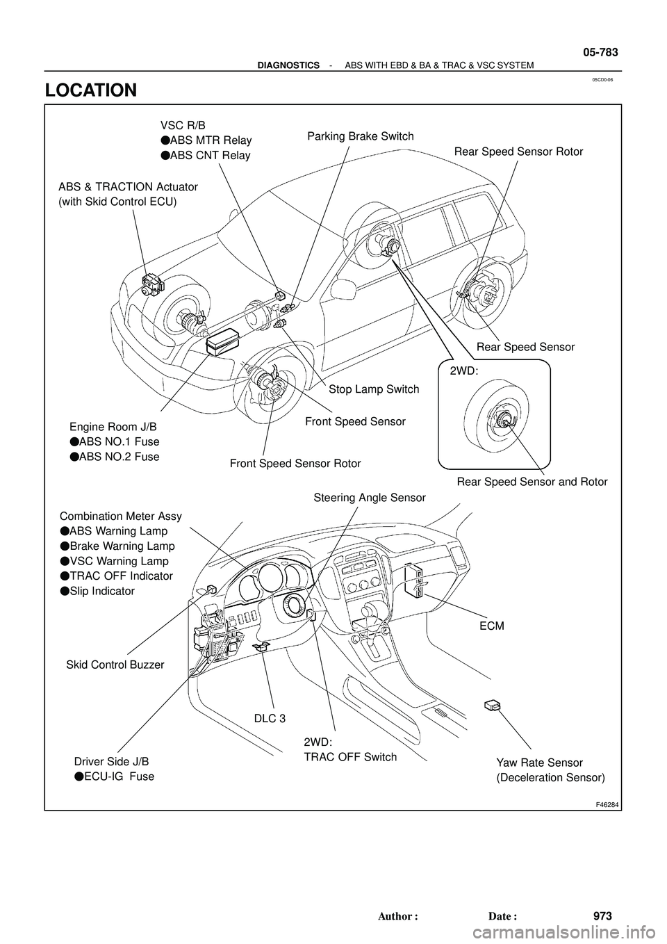
05CD0-06
F46284
Rear Speed Sensor and Rotor
ABS & TRACTION Actuator
(with Skid Control ECU)
Engine Room J/B
�ABS NO.1 Fuse
�ABS NO.2 Fuse
Combination Meter Assy
�ABS Warning Lamp
�Brake Warning Lamp
�VSC Warning Lamp
�TRAC OFF Indicator
�Slip Indicator
Driver Side J/B
�ECU-IG FuseStop Lamp Switch
2WD:
TRAC OFF Switch DLC 3
VSC R/B
�ABS MTR Relay
�ABS CNT Relay
Yaw Rate Sensor
(Deceleration Sensor)
ECM
Steering Angle Sensor
Skid Control Buzzer
Front Speed Sensor
Front Speed Sensor Rotor
2WD:
Parking Brake Switch
Rear Speed Sensor Rear Speed Sensor Rotor
- DIAGNOSTICSABS WITH EBD & BA & TRAC & VSC SYSTEM
05-783
973 Author�: Date�:
LOCATION
Page 2331 of 2572
051ZI-15
A90309
Fuel Pump
Charcoal Canister Assy ECMCombination Meter Assy Mass Air Flow Sensor
(Including Intake Air Temperature Sensor)
DLC3 Accelerator Pedal Rod Assy
(Accelerator Pedal Position Sensor)
Passenger Side J/BEVAP VSV
Heated Oxygen Sensor
(Bank 1 Sensor 2)
Engine Room R/B No. 2
and Engine Room J/B
� EFI Relay
� STARTER Relay
� EFI NO. 1 Fuse
� EFI NO. 2 Fuse
� ETCS Fuse
� AM2 Fuse
� ALT Fuse
� STARTER Fuse
Crankshaft
Position SensorIgnition Coil
with Igniter
Knock SensorThrottle Body Assy
(Throttle Position
Sensor and Actuator) Camshaft Timing Oil
Control Valve Assy
Camshaft Position Sensor
A/F Sensor
(Bank 1 Sensor 1)
PNP SwitchR/B Sub-assy:
� C/OPN Relay
Instrument Panel J/B Assy
� IGN Fuse
� IG2 Fuse
� STOP
Engine Coolant
Temperature Sensor
InjectorPump Module
Front
05-4
- DIAGNOSTICSSFI SYSTEM (2AZ-FE)
194 Author�: Date�:
2005 HIGHLANDER REPAIR MANUAL (RM1144U)
LOCATION

DLC3 Accelerator Pedal Rod Assy
(Accelerator Pedal Position S")