Page 1640 of 1897
SF06S-03
B09135
Ground Cable
PCV Hose
Air Intake Chamber
Assembly
ECT Sensor
Connector ECT Sender
Gauge Connector
IAC Valve
Connector
VSV Connector for No.2 ACIS
Engine Coolant
Reservoir HoseThrottle Position
Sensor Connector Brake Booster
Vacuum Hose Throttle Body Bracket
Water Outlet PS Pressure Tube
19.5 (200, 14)
39 (400, 19)
15 (150, 11)
43 (440, 32)
Ground Strap
DLC1�Gasket
15 (150, 11)
Grand Strap
Connector
�Gasket
39 (400, 29)
V-Bank Cover
Accelerator CableAir Cleaner Hose
w/ Resonator
Purge Hose
Vacuum Hose
Fuel Hose
Clamp
Heater Hose
Intake Manifold Assembly
Injector Connector x 9
Knock Sensor
Connector
Upper Radiator
Hose
�Gasket
: Specified torque
�Non-reusable part
N´m (kgf´cm, ft´lbf)
�Retainer
Knock Sensor
Water Bypass
Hose
VSV Connector for
EVAP
No.1 Engine
Hanger
VSV Connector
for No.1 ACIS
Throttle Cable
Ground Cable
SF-76
- SFIKNOCK SENSOR
1185 Author�: Date�:
2001 AVALON (RM808U)
KNOCK SENSOR
COMPONENTS
Page 1647 of 1897

FI2553
SST
S04600
Fuel
Pump
Connector
S05039
Plug
SF-2
- SFISFI SYSTEM
1111 Author�: Date�:
2001 AVALON (RM808U)
(b) When installing the battery, be especially careful not to in-
correctly connect the positive (+) and negative (-) cables.
(c) Do not permit parts to receive a severe impact during re-
moval or installation. Handle all SFI parts carefully, espe-
cially the ECM.
(d) Do not be careless during troubleshooting as there are
numerous transistor circuits and even slight terminal con-
tact can cause further troubles.
(e) Do not open the ECM cover.
(f) When inspecting during rainy weather, take care to pre-
vent entry of water. Also, when washing the engine
compartment, prevent water from getting on the SFI parts
and wiring connectors.
(g) Parts should be replaced as an assembly.
(h) Care is required when pulling out and inserting wiring con-
nectors.
(1) Release the lock and pull out the connector, pulling
on the connectors.
(2) Fully insert the connector and check that it is locked.
(i) Use SST for inspection or test of the injector or its wiring
connector.
SST 09842-30070
8. FUEL SYSTEM
(a) When disconnecting the high fuel pressure line, a large
amount of gasoline will spill out, so observe the following
procedures:
(1) Disconnect the fuel pump connector.
(2) Start the engine. After the engine has stopped on
its own, turn the ignition switch to LOCK.
(3) Put a container under the connection.
(4) Slowly loosen the connection.
(5) Disconnect the connection.
(6) Plug the connection with a rubber plug.
Page 1648 of 1897

S05054
New Gasket
FI1654
Fulcrum Length
30 cm
SST
FI6372
CORRECT New O-Ring
Delivery Pipe
Injector Grommet
WRONG
B05295
O-Ring
Grommet
Spacer InsulatorDelivery Pipe
O-Ring
- SFISFI SYSTEM
SF-3
111 2 Author�: Date�:
2001 AVALON (RM808U)
(b) When connecting the union bolt on the high pressure pipe
union, observe the following procedures:
(1) Always use 2 new gaskets.
(2) Tighten the union bolt by hand.
(3) Tighten the union bolt to the specified torque.
Torque: 29 N´m (300 kgf´cm, 21 ft´lbf)
(c) When connecting the flare nut on the high pressure pipe
union, observe the following procedures:
(1) Apply a light coat of engine oil to the flare nut, and
tighten the flare nut by hand.
(2) Using SST, tighten the flare nut to specified torque.
SST 09023-12700
NOTICE:
Do not rotate the fuel pipe, when tightening the flare nut.
Torque: 28 N´m (285 kgf´cm, 21 ft´lbf)
HINT:
Use a torque wrench with a fulcrum length of 30 cm (11.81 in.).
(d) Observe the following precautions when removing and
installing the injectors.
(1) Never reuse the O-ring.
(2) When placing a new O-ring on the injector, take
care not to damage it in any way.
(3) Coat a new O-ring with spindle oil or gasoline be-
fore installing-never use engine, gear or brake oil.
(e) Install the injector to the delivery pipe and intake manifold
as shown in the illustration.
(f) Observe these precautions when disconnecting the fuel
tube connector (quick type).
(1) Check if there is any dirt like mud on the pipe and
around the connector before disconnecting them
and clean the dirt away.
(2) Be sure to disconnect with hands.
Page 1670 of 1897
SF101-02
B08628
Charcoal CanisterVapor Pressure Sensor
(Type A)Vapor Pressure Sensor
(Type B)
Vapor Pressure Sensor
Connector
Vacuum Hose
Fuel Hose
Vacuum Hose SF-74
- SFIVAPOR PRESSURE SENSOR
1183 Author�: Date�:
2001 AVALON (RM808U)
VAPOR PRESSURE SENSOR
COMPONENTS
Page 1671 of 1897

SF06R-03
B08629
Disconnect
VC
E2Voltmeter
B08630
Type B
VacuumVacuum
PTNK E2 ECM Type A
Disconnect
DisconnectPressure
Pressure
- SFIVAPOR PRESSURE SENSOR
SF-75
1184 Author�: Date�:
2001 AVALON (RM808U)
INSPECTION
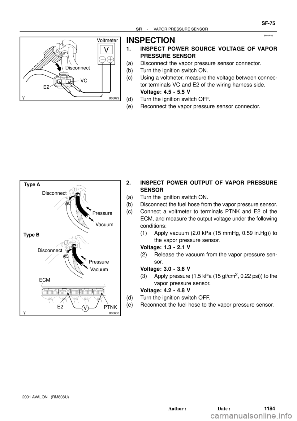
1. INSPECT POWER SOURCE VOLTAGE OF VAPOR
PRESSURE SENSOR
(a) Disconnect the vapor pressure sensor connector.
(b) Turn the ignition switch ON.
(c) Using a voltmeter, measure the voltage between connec-
tor terminals VC and E2 of the wiring harness side.
Voltage: 4.5 - 5.5 V
(d) Turn the ignition switch OFF.
(e) Reconnect the vapor pressure sensor connector.
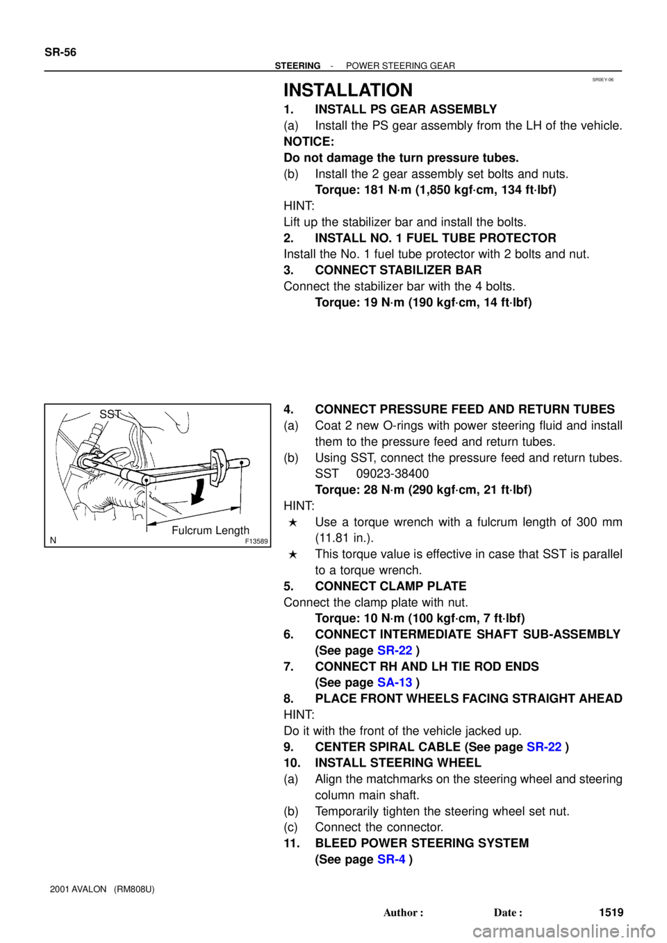
2. INSPECT POWER OUTPUT OF VAPOR PRESSURE
SENSOR
(a) Turn the ignition switch ON.
(b) Disconnect the fuel hose from the vapor pressure sensor.
(c) Connect a voltmeter to terminals PTNK and E2 of the
ECM, and measure the output voltage under the following
conditions:
(1) Apply vacuum (2.0 kPa (15 mmHg, 0.59 in.Hg)) to
the vapor pressure sensor.
Voltage: 1.3 - 2.1 V
(2) Release the vacuum from the vapor pressure sen-
sor.
Voltage: 3.0 - 3.6 V
(3) Apply pressure (1.5 kPa (15 gf/cm
2, 0.22 psi)) to the
vapor pressure sensor.
Voltage: 4.2 - 4.8 V
(d) Turn the ignition switch OFF.
(e) Reconnect the fuel hose to the vapor pressure sensor.
Page 1781 of 1897
SR0ET-05
F09931
Stabilizer Bar
Clamp PlateNo. 1 Fuel Tube Protector
Intermediate Shaft
Sub-assembly
Return Tube
Pressure Feed Tube
PS Gear Assembly
* For use with SSTCotter Pin � Non-reusable part
19 (190, 14)
19 (190, 14)
10 (100, 7)
35 (360, 26)
181 (1,850, 134)
181 (1,850, 134)
49 (500, 36)
49 (500, 36)N´m (kgf´cm, ft´lbf) : Specified torque
25 (250, 18)
*28 (290, 21)
Cotter Pin25 (250, 18)
*28 (290, 21)
O-Ring �
Power steering fluid�
�
- STEERINGPOWER STEERING GEAR
SR-37
1500 Author�: Date�:
2001 AVALON (RM808U)
POWER STEERING GEAR
COMPONENTS
Page 1789 of 1897

SR0EY-06
F13589
SST
Fulcrum Length
SR-56
- STEERINGPOWER STEERING GEAR
1519 Author�: Date�:
2001 AVALON (RM808U)
INSTALLATION
1. INSTALL PS GEAR ASSEMBLY
(a) Install the PS gear assembly from the LH of the vehicle.
NOTICE:
Do not damage the turn pressure tubes.
(b) Install the 2 gear assembly set bolts and nuts.
Torque: 181 N´m (1,850 kgf´cm, 134 ft´lbf)
HINT:
Lift up the stabilizer bar and install the bolts.
2. INSTALL NO. 1 FUEL TUBE PROTECTOR
Install the No. 1 fuel tube protector with 2 bolts and nut.
3. CONNECT STABILIZER BAR
Connect the stabilizer bar with the 4 bolts.
Torque: 19 N´m (190 kgf´cm, 14 ft´lbf)
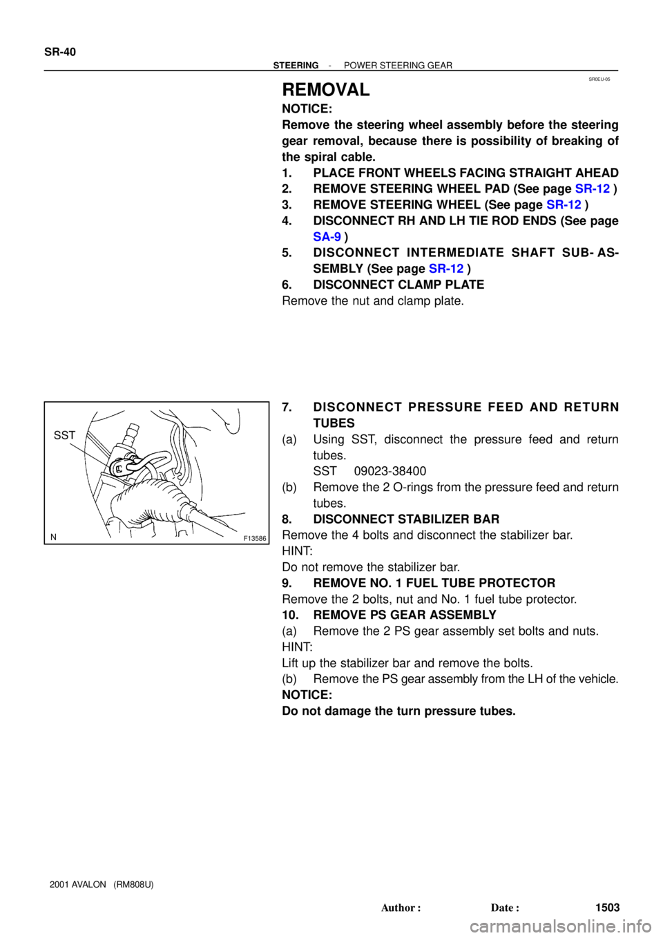
4. CONNECT PRESSURE FEED AND RETURN TUBES
(a) Coat 2 new O-rings with power steering fluid and install
them to the pressure feed and return tubes.
(b) Using SST, connect the pressure feed and return tubes.
SST 09023-38400
Torque: 28 N´m (290 kgf´cm, 21 ft´lbf)
HINT:
�Use a torque wrench with a fulcrum length of 300 mm
(11.81 in.).
�This torque value is effective in case that SST is parallel
to a torque wrench.
5. CONNECT CLAMP PLATE
Connect the clamp plate with nut.
Torque: 10 N´m (100 kgf´cm, 7 ft´lbf)
6. CONNECT INTERMEDIATE SHAFT SUB-ASSEMBLY
(See page SR-22)
7. CONNECT RH AND LH TIE ROD ENDS
(See page SA-13)
8. PLACE FRONT WHEELS FACING STRAIGHT AHEAD
HINT:
Do it with the front of the vehicle jacked up.
9. CENTER SPIRAL CABLE (See page SR-22)
10. INSTALL STEERING WHEEL
(a) Align the matchmarks on the steering wheel and steering
column main shaft.
(b) Temporarily tighten the steering wheel set nut.
(c) Connect the connector.
11. BLEED POWER STEERING SYSTEM
(See page SR-4)
Page 1798 of 1897

SR0EU-05
F13586
SST
SR-40
- STEERINGPOWER STEERING GEAR
1503 Author�: Date�:
2001 AVALON (RM808U)
REMOVAL
NOTICE:
Remove the steering wheel assembly before the steering
gear removal, because there is possibility of breaking of
the spiral cable.
1. PLACE FRONT WHEELS FACING STRAIGHT AHEAD
2. REMOVE STEERING WHEEL PAD (See page SR-12)
3. REMOVE STEERING WHEEL (See page SR-12)
4. DISCONNECT RH AND LH TIE ROD ENDS (See page
SA-9)
5. DISCONNECT INTERMEDIATE SHAFT SUB- AS-
SEMBLY (See page SR-12)
6. DISCONNECT CLAMP PLATE
Remove the nut and clamp plate.
7. DISCONNECT PRESSURE FEED AND RETURN
TUBES
(a) Using SST, disconnect the pressure feed and return
tubes.
SST 09023-38400
(b) Remove the 2 O-rings from the pressure feed and return
tubes.
8. DISCONNECT STABILIZER BAR
Remove the 4 bolts and disconnect the stabilizer bar.
HINT:
Do not remove the stabilizer bar.
9. REMOVE NO. 1 FUEL TUBE PROTECTOR
Remove the 2 bolts, nut and No. 1 fuel tube protector.
10. REMOVE PS GEAR ASSEMBLY
(a) Remove the 2 PS gear assembly set bolts and nuts.
HINT:
Lift up the stabilizer bar and remove the bolts.
(b) Remove the PS gear assembly from the LH of the vehicle.
NOTICE:
Do not damage the turn pressure tubes.