Page 250 of 1897
BE0HV-04
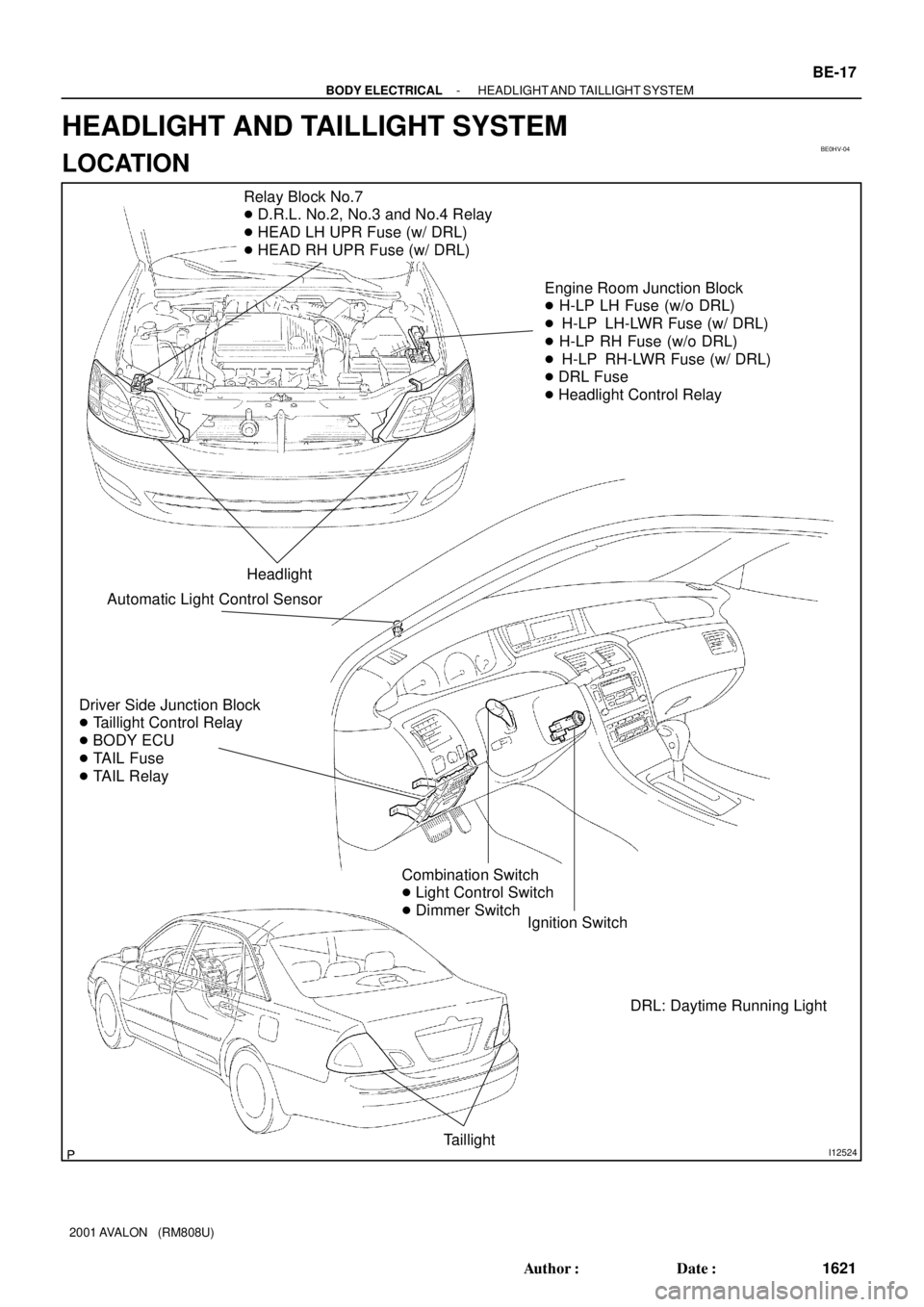
I12524
Relay Block No.7
� D.R.L. No.2, No.3 and No.4 Relay
� HEAD LH UPR Fuse (w/ DRL)
� HEAD RH UPR Fuse (w/ DRL)
Engine Room Junction Block
� H-LP LH Fuse (w/o DRL)
� H-LP LH-LWR Fuse (w/ DRL)
� H-LP RH Fuse (w/o DRL)
� H-LP RH-LWR Fuse (w/ DRL)
� DRL Fuse
� Headlight Control Relay
Headlight
Driver Side Junction Block
� Taillight Control Relay
� BODY ECU
� TAIL Fuse
� TAIL Relay
Ignition Switch
Taillight
Combination Switch
� Light Control Switch
� Dimmer Switch
Automatic Light Control Sensor
DRL: Daytime Running Light
- BODY ELECTRICALHEADLIGHT AND TAILLIGHT SYSTEM
BE-17
1621 Author�: Date�:
2001 AVALON (RM808U)
HEADLIGHT AND TAILLIGHT SYSTEM
LOCATION
Page 251 of 1897

INSPECT")
BE1DL-01
I13328
w/ Sliding roof:
w/o Sliding roof:
N12373
ON
N20159
ON
OFFOhmmeter
I13329
ON
OFF
Z07389
- BODY ELECTRICALINTERIOR LIGHT SYSTEM
BE-31
1635 Author�: Date�:
2001 AVALON (RM808U)
INSPECTION
1. INSPECT FRONT PERSONAL LIGHT CONTINUITY
Switch positionTester connectionSpecified condition
OFF1 - 3No continuity
-2 - 3No continuity
ON1 - 3Continuity
If continuity is not as specified, replace the light assembly or
bulb.
2. INSPECT REAR INTERIOR LIGHT CONTINUITY
Switch positionTester connectionSpecified condition
OFF1 - 2No continuity
ON1 - 2Continuity
If continuity is not as specified, replace a bulb or rear personal
light.
3. INSPECT DOOR COURTESY SWITCH CONTINUITY
(a) Check that continuity exists between terminal and the
switch body with the switch ON (switch pin released:
opened door).
(b) Check that no continuity exists between terminal and the
switch body withe the swtich OFF (switch pin pushed in:
closed doors).
If operation is not as specified, replace the switch.
4. INSPECT VANITY LIGHT CONTINUITY
Switch positionTester connectionSpecified condition
OFF1 - 2No continuity
ON1 - 2Continuity
If continuity is not as specified, replace bulb or vanity light.
5. INSPECT LUGGAGE COMPARTMENT LIGHT CONTI-
NUITY
Switch positionTester connectionSpecified condition
OFF-No continuity
ON1 - 2Continuity
If continuity is not as specified, replace the light.
Page 252 of 1897
Z05876
ON
OFF
I14261
1
N01732
2
1 BE-32
- BODY ELECTRICALINTERIOR LIGHT SYSTEM
1636 Author�: Date�:
2001 AVALON (RM808U)
6. INSPECT LUGGAGE COMPARTMENT DOOR COUR-
TESY SWITCH CONTINUITY
ConditionTester connectionSpecified condition
OFF-No continuity
ON1 - Switch bodyContinuity
If operation is not as specified, replace the switch.
7. INSPECT INTERIOR LIGHT ASSEMBLY CONTINUITY
(a) Disconnect the connector from room light assembly.
(b) Turn the room light switch ON, check that there is continu-
ity between terminal 1 and body ground.
(c) Turn the room light switch DOOR, check that there is con-
tinuity between terminal 1 and 2.
If operation is not as specified, replace the switch.
8. INSPECT ILLMINATION ENTRY SYSTEM
(See Page BE-2)
Page 253 of 1897
BE0I2-03
I12527
Front Personal Light
Vanity LightInterior Light Assembly
Door Courtesy LightDoor Courtesy Switch
Door Courtesy Light
Door Courtesy Switch
Driver Side Junction Block
� DOME Fuse
� Body ECU
Rear Interior Light Assembly
Luggage Compartment Light
BE-30
- BODY ELECTRICALINTERIOR LIGHT SYSTEM
1634 Author�: Date�:
2001 AVALON (RM808U)
INTERIOR LIGHT SYSTEM
LOCATION
Page 267 of 1897

5. INSPECT MIRROR SWI")
N21376
Wire Harness Side
123 4 56 78910
h-10-1-c
N13659
6
5
I13295
1
2
I13296
1
2
- BODY ELECTRICALPOWER MIRROR CONTROL SYSTEM
BE-1 15
1719 Author�: Date�:
2001 AVALON (RM808U)
5. INSPECT MIRROR SWITCH CIRCUIT
Disconnect the connector from the switch and inspect the con-
nector on the wire harness side.
Tester connectionConditionSpecified condition
8 - GroundConstantContinuity
4 - GroundIgnition switch position LOCKNo voltage
4 - GroundIgnition switch position ACC or ONBattery voltage
If the circuit is not as specified, inspect the circuits connected
to other parts.
6. INSPECT MIRROR SWITCH INDICATOR LIGHT OP-
ERATION
Connect the positive (+) lead from the battery to terminal 5 and
the negative (-) lead to terminal 6, and check that the indicator
light does not light up, replace the switch.
7. w/o Mirror defogger and driving position memory:
INSPECT MIRROR MOTOR OPERATION
(a) Connect the positive (+) lead from the battery to terminal
1 and the negative (-) lead to terminal 2, and check that
the mirror turns to the left side.
(b) Reverse the polarity, and check that the mirror turns to the
right side.
Page 275 of 1897

I12519
1. MAIN Fuse - 40 A
2. RDI Fuse - 30 A
3. CDS Fuse - 30 A
4. HAZ Fuse - 15 A
5. SRS WRN Fuse - 5 A
6. DCC 1 Fuse - 30 A
7. ALT-S Fuse - 5 A
8. AM2 Fuse - 10 A
9. HORN Fuse - 10 A
10. DOOR NO. 2 Fuse - 15 A
11. A/F Fuse - 25 A
12. IG2 Fuse - 15 A
13. EFI NO. 1 Fuse - 15 A
14. ABS NO. 2 Fuse - 25 A
15. ABS NO. 3 Fuse - 25 A
16. EFI NO. 2 Fuse - 7.5 A
17. ALT Fuse - 120 A
18. ABS Fuse - 60 A
19. DRL Fuse - 7.5 A
20. ABS NO. 4 Fuse - 5 A
21. HTR Fuse - 50 A
22. AM1 Fuse - 40 AEngine Room Junction Block:
1
A
D
G 2
B
E
H 3
C
F
1011
1213141516
98
45
29
28
67
20
27
30
19
2625
2324
23. H-LP LH Fuse - 15 A *2
24. H-LP RH Fuse - 15 A *2
25. H-LP LH LWR Fuse - 15 A *1
26. H-LP RH LWR Fuse - 15 A *1
27. SPARE Fuse - 10 A
28. SPARE Fuse - 15 A
29. SPARE Fuse - 25 A
30. SPARE Fuse - 30 AA. MG/CLT Relay
B. A/F Relay
C. HORN Relay
D. EFI Relay
E. IG2 Relay
F. ST Relay
G. HEAD Relay
H. HTR Relay Relays: Fuses:
*1: w/ Daytime Running Light
*2: w/o Daytime Running Light 1718
21 22
BE-10
- BODY ELECTRICALPOWER SOURCE
1614 Author�: Date�:
2001 AVALON (RM808U)
Page 277 of 1897
I12520
1.HEAD LH UPR Fuse - 10 A *1
2. HEAD RH UPR Fuse - 10 A *1
A. DRL NO. 3 Relay *1
B. DRL NO. 4 Relay *1
C. DRL NO. 2 Relay *1 Relays: Fuses:
A. FAN NO. 3 Relay
B. ABS-MTR Relay
C. FAN NO. 2 Relay
D. ABS-SOL Relay
E. FAN NO. 1 Relay Relays: Relay Block No. 8: Relay Block No. 7:
1 A
D
2B
EC
A
B
C
*1: w/ Daytime Running Light System (w/ Day time running light) BE-12
- BODY ELECTRICALPOWER SOURCE
1616 Author�: Date�:
2001 AVALON (RM808U)
Page 298 of 1897

INSPECTION
1. A/C c")
BE1EF-02
I12827
2 25
24 12
1
I12828
2 25
24 12
1ON
I12829
2 26
24 13
1
I12830
2 26
24 13
1
ON BE-122
- BODY ELECTRICALSEAT HEATER SYSTEM
1726 Author�: Date�:
2001 AVALON (RM808U)
INSPECTION
1. A/C control panel assembly:
INSPECT DRIVERS SEAT HEATER SWITCH OPERA-
TION
(a) Connect the positive (+) lead from the battery to terminal
1, 2 and negative (-) lead to terminal 24, 25.
(b) Connect the positive (+) lead from the battery to terminal
12 through a 1.4 W test bulb.
(c) Turn the drivers seat heater switch ON and check that the
test bulb and indicator light turn ON.
If operation is not as specified, proceed to the next inspection.
2. A/C control panel assembly:
INSPECT PASSENGER SEAT HEATER SWITCH OP-
ERATION
(a) Connect the positive (+) lead from the battery to terminal
1, 2 and negative (-) lead to terminal 24, 26.
(b) Connect the positive (+) lead from the battery to terminal
13 through a 1.4 W test bulb.
(c) Turn the passenger seat heater switch ON and check that
the test bulb and indicator light turn ON.
If operation is not as specified, proceed to the next inspection.