Page 1296 of 1897

NOTICE:
Pull up the main bearing cap little by little to")
S06200
Joint Surface
P12495
P12980
Plastigage
P12954
P12993
EM-88
- ENGINE MECHANICALCYLINDER BLOCK
1072 Author�: Date�:
2001 AVALON (RM808U)
NOTICE:
Pull up the main bearing cap little by little to the right and
the left by turns and pay attention not to damage the joint
surface of the cylinder block and the main bearing cap.
HINT:
�Keep the lower bearing and main bearing cap together.
�Arrange the main bearing caps and lower thrust washers
in correct order.
(d) Lift out the crankshaft.
HINT:
Keep the upper bearings together with the cylinder block.
(e) Clean each main journal and bearing.
(f) Check each main journal and bearing for pitting and
scratches.
If the journal or bearing is damaged, replace the bearings. If
necessary, replace the crankshaft.
(g) Place the crankshaft on the cylinder block.
(h) Lay a strip of Plastigage across each journal.
(i) Install the 4 main bearing caps. (See page EM-101)
Torque:
12 pointed head bolts:
1st: 22 N´m (225 kgf´cm, 16 ft´lbf)
2nd: Turn extra 90°
Hexagon head bolts:
27 N´m (275 kgf´cm, 20 ft´lbf)
NOTICE:
Do not turn the crankshaft.
(j) Remove the main bearing caps. (See steps (a) to (c) )
(k) Measure the Plastigage at its widest point.
Standard oil clearance:
No.1 and No.4 journals0.014 - 0.034 mm (0.0006 - 0.0013 in.)
No.2 and No.3 journals0.026 - 0.046 mm (0.0010 - 0.0018 in.)
Maximum clearance:
No.1 and No.4 journals0.05 mm (0.0020 in.)
No.2 and No.3 journals0.06 mm (0.0024 in.)
If the oil clearance is greater than maximum, replace the bear-
ings. If necessary, replace the crankshaft.
Page 1300 of 1897
P12404
P12405A09698
P12403
P12416
60°C
P12415
EM-92
- ENGINE MECHANICALCYLINDER BLOCK
1076 Author�: Date�:
2001 AVALON (RM808U)
32. CHECK FIT BETWEEN PISTON AND PISTON PIN
Try to move the piston back and forth on the piston pin.
If any movement is felt, replace the piston and pin as a set.
33. REMOVE PISTON RINGS
(a) Using a piston ring expander, remove the 2 compression
rings.
(b) Remove the 2 side rails and oil ring by hand.
HINT:
Arrange the piston rings in the correct order only.
34. DISCONNECT CONNECTING ROD FROM PISTON
(a) Using a small screwdriver, pry out the 2 snap rings.
(b) Gradually heat the piston to approx. 60°C (140°F).
(c) Using a plastic-faced hammer and brass bar, lightly tap
out the piston pin and remove the connecting rod.
HINT:
�The piston and pin are a matched set.
�Arrange the pistons, pins, rings, connecting rods and
bearings in the correct order.
Page 1304 of 1897

11. INSPECT PISTON RING END GAP
(a) Insert the piston ring into the cylinder bore")
P12583
105 mm
EM7639
P12506
Z04012
EM-96
- ENGINE MECHANICALCYLINDER BLOCK
1080 Author�: Date�:
2001 AVALON (RM808U)
11. INSPECT PISTON RING END GAP
(a) Insert the piston ring into the cylinder bore.
(b) Using a piston, push the piston ring a little beyond the bot-
tom of the ring travel, 105 mm (4.13 in.) from the top of the
cylinder block.
(c) Using a feeler gauge, measure the end gap.
Standard end gap:
No.10.25 - 0.35 mm (0.0098 - 0.0138 in.)
No.20.35 - 0.45 mm (0.0138 - 0.0177 in.) for G2 mark
0.55 - 0.65 mm (0.0217 - 0.0256 in.) for 2T mark
Oil (Side rail)0.15 - 0.40 mm (0.0059 - 0.0157 in.)
Maximum end gap:
No.10.95 mm (0.0374 in.)
No.21.05 mm (0.0413 in.) for G2 mark
1.25 mm (0.0492 in.) for 2T mark
Oil (Side rail)1.00 mm (0.0394 in.)
If the end gap is greater than maximum, replace the piston ring.
If the end gap is greater than maximum, even with a new piston
ring, replace the cylinder block.
12. INSPECT PISTON PIN FIT
At 60°C (140°F), you should be able to push the piston pin into
the piston pin hole with your thumb.
13. INSPECT CONNECTING ROD ALIGNMENT
Using a rod aligner and feeler gauge, check the connecting rod
alignment.
�Check for out-of-alignment.
Maximum out-of-alignment:
0.05 mm (0.0020 in.) per 100 mm (3.94 in.)
If bend is greater than maximum, replace the connecting rod as-
sembly.
Page 1305 of 1897

�Check for twist
Maximum twist:
0.15 mm (0.0059 in.) per 100 mm (3.94 in.)
If twi")
Z04011
EM6525
EM0227
EM6347
P12406
- ENGINE MECHANICALCYLINDER BLOCK
EM-97
1081 Author�: Date�:
2001 AVALON (RM808U)
�Check for twist
Maximum twist:
0.15 mm (0.0059 in.) per 100 mm (3.94 in.)
If twist is greater than maximum, replace the connecting rod as-
sembly.
14. INSPECT PISTON PIN OIL CLEARANCE
(a) Using a caliper gauge, measure the inside diameter of the
connecting rod bushing.
Bushing inside diameter:
22.005 - 22.014 mm (0.8663 - 0.8667 in.)
(b) Using a micrometer, measure the piston pin diameter.
Piston pin diameter:
21.997 - 22.006 mm (0.8660 - 0.8664 in.)
(c) Subtract the piston pin diameter measurement from the
bushing inside diameter measurement.
Standard oil clearance:
0.005 - 0.011 mm (0.0002 - 0.0004 in.)
Maximum oil clearance: 0.05 mm (0.0020 in.)
15. INSPECT CONNECTING ROD BOLTS
Using vernier calipers, measure the tension portion diameter of
the bolt.
Standard diameter: 7.2 - 7.3 mm (0.284 - 0.287 in.)
Minimum diameter: 7.0 mm (0.276 in.)
If the diameter is less than minimum, replace the bolt.
16. INSPECT CRANKSHAFT FOR CIRCLE RUNOUT
(a) Place the crankshaft on V-blocks.
(b) Using a dial indicator, measure the circle runout, as
shown in the illustration.
Maximum circle runout: 0.06 mm (0.0024 in.)
If the circle runout is greater than maximum, replace the crank-
shaft.
Page 1306 of 1897
P12493
EM-98
- ENGINE MECHANICALCYLINDER BLOCK
1082 Author�: Date�:
2001 AVALON (RM808U)
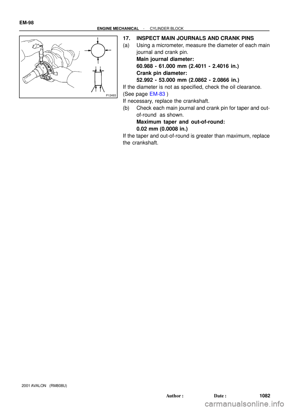
17. INSPECT MAIN JOURNALS AND CRANK PINS
(a) Using a micrometer, measure the diameter of each main
journal and crank pin.
Main journal diameter:
60.988 - 61.000 mm (2.4011 - 2.4016 in.)
Crank pin diameter:
52.992 - 53.000 mm (2.0862 - 2.0866 in.)
If the diameter is not as specified, check the oil clearance.
(See page EM-83)
If necessary, replace the crankshaft.
(b) Check each main journal and crank pin for taper and out-
of-round as shown.
Maximum taper and out-of-round:
0.02 mm (0.0008 in.)
If the taper and out-of-round is greater than maximum, replace
the crankshaft.
Page 1310 of 1897

(b")
A10530
A09696
Less than 6 mm
A10529
P12753
10 11
12 13
14
151
162
3
45
6
7
89
P25741
Painted Mark
Front90°
90° EM-104
- ENGINE MECHANICALCYLINDER BLOCK
1088 Author�: Date�:
2001 AVALON (RM808U)
(b) Temporarily place the 4 main bearing caps level and let
them in their proper locations.
(c) Apply a light coat of engine oil on the threads and under
the main bearing cap bolts for the 12 pointed head.
(d) Temporarily install the 8 main bearing cap bolts to the in-
side positions.
(e) Insert the main bearing cap with your hand until the clear-
ance between the main bearing cap and the cylinder
block will become less than 6 mm (0.23 in.) by making the
2 internal main bearing cap bolts as a guide.
(f) Using a plastic-faced hammer, lightly tap the bearing cap
to ensure a proper fit.
8. INSTALL 12 POINTED HEAD MAIN BEARING CAP
BOLTS
HINT:
�The main bearing cap bolts are tightened in 2 progressive
steps (steps (b) and (d)).
�If any of the main bearing cap bolts is broken or deformed,
replace it.
(a) Apply a light coat of engine oil on the threads and under
the main bearing cap bolts.
(b) Install and uniformly tighten the 16 main bearing cap bolts
in several passes and in the sequence shown.
Torque: 22 N´m (225 kgf´cm, 16 ft´lbf)
If any of the main bearing cap bolts does not meet the torque
specification, replace the main bearing cap bolt.
(c) Mark the front of the main bearing cap bolts with paint.
(d) Retighten the main bearing cap bolts by 90° in the numer-
ical order shown.
(e) Check that the painted mark is now at a 90° angle to the
front.
Page 1312 of 1897

(a) Apply a light coat of engine oil")
P12697
P25743
Painted Mark
Front90°
90°
P12911
Seal Width
2 - 3 mm A
BA
B EM-106
- ENGINE MECHANICALCYLINDER BLOCK
1090 Author�: Date�:
2001 AVALON (RM808U)
(a) Apply a light coat of engine oil on the threads and under
the heads of the connecting rod cap bolts.
(b) Install and alternately tighten the 2 connecting rod cap
bolts in several passes.
Torque: 24.5 N´m (250 kgf´cm, 18 ft´lbf)
If any of the connecting rod cap bolts does not meet the torque
specification, replace the connecting rod cap bolts.
(c) Mark the front of the connecting cap bolts with paint.
(d) Retighten the cap bolts by 90° as shown.
(e) Check that the painted mark is now at a 90° angle to the
front.
(f) Check that the crankshaft turns smoothly.
14. CHECK CONNECTING ROD THRUST CLEARANCE
(See page EM-83)
15. INSTALL REAR OIL SEAL RETAINER
(a) Remove any old packing (FIPG) material and be careful
not to drop any oil on the contact surfaces of the oil seal
retainer and cylinder block.
�Using a razor blade and gasket scraper, remove all
the oil packing (FIPG) material from the gasket sur-
faces and sealing grooves.
�Thoroughly clean all components to remove all the
loose material.
�Using a non-residue solvent, clean both sealing
surfaces.
(b) Apply seal packing to the oil seal retainer as shown in the
illustration.
Seal packing: Part No. 08826-00080 or equivalent
�Install a nozzle that has been cut to a 2 - 3 mm (0.08
- 0.12 in.) opening.
�Parts must be assembled within 3 minutes of ap-
plication. Otherwise the material must be removed
and reapplied.
�Immediately remove nozzle from the tube and rein-
stall cap.
(c) Install the oil seal retainer with the 6 bolts. Uniformly tight-
en the bolt in several passes and in the sequence shown.
Torque: 8 N´m (80 kgf´cm, 69 in.´lbf)
16. INSTALL CYLINDER BLOCK SIDE COVER
Install a new gasket and the cylinder block side cover with the
3 bolts and 2 nuts.
Torque: 9 N´m (90 kgf´cm, 78 in.´lbf)
Page 1316 of 1897
EM0ZP-02
EM6363
SST
EM6364
Oil
Hole
EM6535
P00326
P12589
- ENGINE MECHANICALCYLINDER BLOCK
EM-99
1083 Author�: Date�:
2001 AVALON (RM808U)
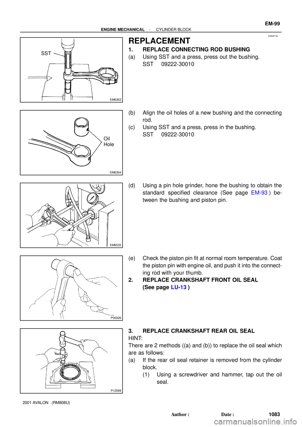
REPLACEMENT
1. REPLACE CONNECTING ROD BUSHING
(a) Using SST and a press, press out the bushing.
SST 09222-30010
(b) Align the oil holes of a new bushing and the connecting
rod.
(c) Using SST and a press, press in the bushing.
SST 09222-30010
(d) Using a pin hole grinder, hone the bushing to obtain the
standard specified clearance (See page EM-93) be-
tween the bushing and piston pin.
(e) Check the piston pin fit at normal room temperature. Coat
the piston pin with engine oil, and push it into the connect-
ing rod with your thumb.
2. REPLACE CRANKSHAFT FRONT OIL SEAL
(See page LU-13)
3. REPLACE CRANKSHAFT REAR OIL SEAL
HINT:
There are 2 methods ((a) and (b)) to replace the oil seal which
are as follows:
(a) If the rear oil seal retainer is removed from the cylinder
block.
(1) Using a screwdriver and hammer, tap out the oil
seal.