Page 1468 of 1897

CHASSIS
INSPECTION
1. INSPECT STEERING LINKAGE
(a) Check the steering wheel free-play (See page SR-8).
(b) Check the")
MA01O-02
B08915
- MAINTENANCECHASSIS
MA-7
49 Author�: Date�:
2001 AVALON (RM808U)
CHASSIS
INSPECTION
1. INSPECT STEERING LINKAGE
(a) Check the steering wheel free-play (See page SR-8).
(b) Check the steering linkage for looseness or damage.
Check that:
�Tie rod ends do not have excessive play.
�Dust seals and boots are not damaged.
�Boot clamps are not loose.
2. INSPECT SRS AIRBAG (See pages RS-15, RS-30)
3. INSPECT STEERING GEAR HOUSING OIL
Check the steering gear housing for oil leakage.
4. INSPECT DRIVE SHAFT BOOTS
Check the drive shaft boots for clamp looseness, leakage or
damage.
5. INSPECT BALL JOINTS AND DUST COVERS
(a) Inspect the ball joints for excessive looseness.
�Jack up the front of the vehicle and place wooden
blocks with a height of 180 - 200 mm (7.09 - 7.87
in.) under the front tires.
�Lower the jack until there is about half a load on the
front coil spring. Place stands under the vehicle for
safety.
�Check that the front wheels are pointing straight
ahead, and block them with chocks.
�Using a lever, pry up the end of the lower arm, and
check the amount of play.
Maximum ball joint vertical play: 0 mm (0 in.)
If there is play, replace the ball joint.
(b) Check the dust cover for damage.
6. CHECK TRANSAXLE FLUID
Visually check the transaxle for fluid leakage.
If leakage is found, check for the cause and repair.
7. REPLACE TRANSAXLE FLUID (See page DI-160)
Page 1469 of 1897
MA01M-02
P00495
Inside Outside
- MAINTENANCEENGINE
MA-5
47 Author�: Date�:
2001 AVALON (RM808U)
ENGINE
INSPECTION
HINT:
Inspect these items when the engine is cold.
1. REPLACE TIMING BELT (See page EM-15)
2. INSPECT DRIVE BELTS
(See pages CH-1, SR-3 and AC-17)
3. REPLACE SPARK PLUGS (See page IG-1)
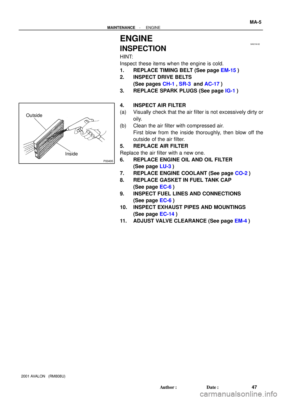
4. INSPECT AIR FILTER
(a) Visually check that the air filter is not excessively dirty or
oily.
(b) Clean the air filter with compressed air.
First blow from the inside thoroughly, then blow off the
outside of the air filter.
5. REPLACE AIR FILTER
Replace the air filter with a new one.
6. REPLACE ENGINE OIL AND OIL FILTER
(See page LU-3)
7. REPLACE ENGINE COOLANT (See page CO-2)
8. REPLACE GASKET IN FUEL TANK CAP
(See page EC-6)
9. INSPECT FUEL LINES AND CONNECTIONS
(See page EC-6)
10. INSPECT EXHAUST PIPES AND MOUNTINGS
(See page EC-14)
11. ADJUST VALVE CLEARANCE (See page EM-4)
Page 1474 of 1897

OUTSIDE VEHICLE
GENERAL MAINTENANCE
These are maintenance and inspection items which are considered to be the owner")
MA001-12
- MAINTENANCEOUTSIDE VEHICLE
MA-1
43 Author�: Date�:
2001 AVALON (RM808U)
OUTSIDE VEHICLE
GENERAL MAINTENANCE
These are maintenance and inspection items which are considered to be the owner's responsibility.
They can be done by the owner or they can have them done at a service shop.
These items include those which should be checked on a daily basis, those which, in most cases, do not
require (special) tools and those which are considered to be reasonable for the owner to do.
Items and procedures for general maintenance are as follows.
1. GENERAL NOTES
�Maintenance items may vary from country to country. Check the owner's manual supplement in which
the maintenance schedule is shown.
�Every service item in the periodic maintenance schedule must be performed.
�Periodic maintenance service must be performed according to whichever interval in the periodic main-
tenance schedule occurs first, the odometer reading (miles) or the time interval (months).
�Maintenance service after the last period should be performed at the same interval as before unless
otherwise noted.
�Failure to do even one item an cause the engine to run poorly and increase exhaust emissions.
2. TIRES
(a) Check the pressure with a gauge. If necessary, adjust.
(b) Check for cuts, damage or excessive wear.
3. WHEEL NUTS
When checking the tires, check the nuts for looseness or for missing nuts. If necessary, tighten them.
4. TIRE ROTATION
Check the owner's manual supplement in which the maintenance schedule is shown.
5. WINDSHIELD WIPER BLADES
Check for wear or cracks whenever they do not wipe clean. If necessary, replace.
6. FLUID LEAKS
(a) Check underneath for leaking fuel, oil, water or other fluid.
(b) If you smell gasoline fumes or notice any leak, have the cause found and corrected.
7. DOORS AND ENGINE HOOD
(a) Check that all doors including the trunk lid operate smoothly, and that all latches lock securely.
(b) Check that the engine hood secondary latch secures the hood from opening when the primary latch
is released.
Page 1475 of 1897

UNDER HOOD
GENERAL MAINTENANCE
1. GENERAL NOTES
�Maintenance items may vary from country to country. Check the owners")
MA003-12
MA-4
- MAINTENANCEUNDER HOOD
46 Author�: Date�:
2001 AVALON (RM808U)
UNDER HOOD
GENERAL MAINTENANCE
1. GENERAL NOTES
�Maintenance items may vary from country to country. Check the owner's manual supplement in which
the maintenance schedule is shown.
�Every service item in the periodic maintenance schedule must be performed.
�Periodic maintenance service must be performed according to whichever interval in the periodic main-
tenance schedule occurs first, the odometer reading (miles) or the time interval (months).
�Maintenance service after the last period should be performed at the same interval as before unless
otherwise noted.
�Failure to do even one item an cause the engine to run poorly and increase exhaust emissions.
2. WINDSHIELD WASHER FLUID
Check that there is sufficient fluid in the tank.
3. ENGINE COOLANT LEVEL
Check that the coolant level is between the ºFULLº and ºLOWº lines on the see-through reservoir.
4. RADIATOR AND HOSES
(a) Check that the front of the radiator is clean and not blocked with leaves, dirt or bugs.
(b) Check the hoses for cracks, kinks, rot or loose connections.
5. BATTERY ELECTROLYTE LEVEL
Check that the electrolyte level of all battery cells is between the upper and lower level lines on the case.
6. BRAKE FLUID LEVEL
Check that the brake fluid level is near the upper level line on the see-through reservoirs.
7. ENGINE DRIVE BELTS
Check drive belt for fraying, cracks, wear or oiliness.
8. ENGINE OIL LEVEL
Check the level on the dipstick with the engine turned off.
9. POWER STEERING FLUID LEVEL
�Check the level.
�The level should be in the ºHOTº or ºCOLDº range depending on the fluid temperature.
10. AUTOMATIC TRANSMISSION FLUID LEVEL
(a) Park the vehicle on a level surface.
(b) With the engine idling and the parking brake applied, shift the selector into all positions from ºPº to ºLº,
and then shift into ºPº position.
(c) Pull out the dipstick and wipe off the fluid with a clean rag. Re-insert the dipstick and check that the
fluid level is in the ºHOTº range.
(d) Do this check with the fluid at normal driving temperature (70 - 80°C, 158 - 176°F).
HINT:
Wait until the engine cools down (approx. 30 min.) before checking the fluid level after extended driving at
high speeds, in hot weather, in heavy traffic or pulling a trailer.
11. EXHAUST SYSTEM
If any change in the sound of the exhaust or smell of the exhaust fumes is noticed, have the cause located
and corrected.
Page 1514 of 1897
- PREPARATIONENGINE MECHANICAL
PP-3
53 Author�: Date�:
2001 AVALON (RM808U)
09249-63010Torque Wrench AdaptorRH camshaft timing pulley
09330-00021Companion Flange Holding ToolCrankshaft pulley
09608-03071ReplacerSpark plug tube gasket
09816-30010Oil Pressure Switch SocketKnock sensor
09843-18020Diagnosis Check Wire
09950-50012Puller C Set
(09951-05010)Hanger 150Crankshaft pulley
Crankshaft timing pulley
(09952-05010)Slide ArmCrankshaft pulley
Crankshaft timing pulley
(09953-05010)Center Bolt 100Crankshaft pulley
Crankshaft timing pulley
(09953-05020)Center Bolt 150Crankshaft pulley
Crankshaft timing pulley
(09954-05010)Claw No.1Crankshaft timing pulley
(09954-05020)Claw No.2Crankshaft pulley
09950-70010Handle Set
Page 1601 of 1897
SF0SO-03
B01689
12
Battery positive voltage is applied
Battery positive voltage is cut offValve moves in direction
Valve moves in direction
- SFICAMSHAFT TIMING OIL CONTROL VALVE
SF-51
1160 Author�: Date�:
2001 AVALON (RM808U)
INSPECTION
INSPECT CAMSHAFT OIL CONTROL VALVE OPERATION
Connect the positive (+) lead from the battery to terminal 1 and
negative (-) lead to terminal 2, and check the movement of the
valve.
If operation is not as specified, replace the valve.
Page 1621 of 1897

(p) After checking fuel pressure, disconnect the negative (-)
term")
B09079
B09076
Fuel Hose
Clamp
S04508
Ohmmeter
4
5
S04509
4
5
Battery SF-8
- SFIFUEL PUMP
111 7 Author�: Date�:
2001 AVALON (RM808U)
(p) After checking fuel pressure, disconnect the negative (-)
terminal cable from the battery and carefully remove the
SST and fuel tube connector to prevent gasoline from
splashing.
SST 09268-41047, 09268-45014
(q) Reconnect the No.1 fuel pipe (fuel tube connector).
CAUTION:
Perform connecting operations of the tube connector
(quick type) after observing the precautions (See page
SF-1).
(r) Surely install the hose clamp to the fuel filter with ºclickº
sound.
(s) After installing the clamp, check that the clamp is fixed by
pulling up to the clamp.
(t) Reconnect the negative (-) terminal cable to the battery.
(u) Check for fuel leaks.
3. REMOVE REAR SEAT CUSHION
4. REMOVE FLOOR SERVICE HOLE COVER
5. DISCONNECT FUEL PUMP & SENDER GAUGE CON-
NECTOR
6. INSPECT FUEL PUMP RESISTANCE
Using an ohmmeter, measure the resistance between terminals
4 and 5.
Resistance: 0.2 - 3.0 W at 20°C (68°F)
If the resistance is not as specified, replace the fuel pump.
7. INSPECT FUEL PUMP OPERATION
Connect the positive (+) lead from the battery to terminal 4 of
the connector, and the negative (-) lead to terminal 5. Check
that the fuel pump operates.
NOTICE:
�These tests must be done quickly (within 10 seconds)
to prevent the coil burning out.
�Keep the fuel pump as far away from the battery as
possible.
�Always do the switching at the battery side.
Page 1635 of 1897

SF076-05
B06484
New Insulator
New
O-Ring
New GrommetNew
O-Ring
B06485
Turn
Connector
Push
S04510
Spacer
Spacer
B06614
B06616
Rotate
Outward
- SFIINJECTOR
SF-25
1134 Author�: Date�:
2001 AVALON (RM808U)
INSTALLATION
1. INSTALL INJECTORS AND DELIVERY PIPES
(a) Install new insulator and grommet to each injector.
(b) Apply a light coat of spindle oil or gasoline to 2 new O-
rings and install them to each injector.
(c) Apply a light coat of spindle oil or gasoline on the place
where a delivery pipe touches an O-ring of the injector.
(d) While turning the injector clockwise and counterclock-
wise, push it to the delivery pipes. Install the 6 injectors.
(e) Position the injector connector outward.
(f) Place the 4 spacers in position on the intake manifold.
(g) Apply a light coat of spindle oil or gasoline on the place
where a intake manifold touches an O-ring of the injector.
(h) Place the delivery pipes and fuel pipe together with the 6
injectors in position on the intake manifold.
(i) Temporarily install the 4 bolts holding the delivery pipes
to the intake manifold.
(j) Temporarily install the bolt holding the No.1 fuel pipe to
the intake manifold.
(k) Check that the injectors rotate smoothly.
HINT:
If injectors do not rotate smoothly, the probable cause is incor-
rect installation of O-rings. Replace the O-rings.
(l) Position the injector connector outward.