Page 1593 of 1897
B06677B09120B09122
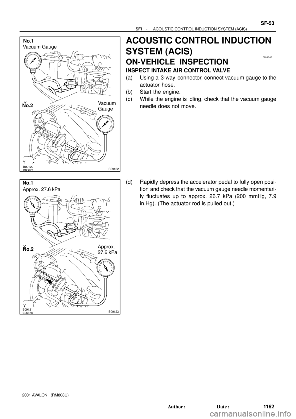
No.2
Vacuum GaugeNo.1
Vacuum
Gauge
SF06B-05
B06678B09121B09123
Approx.
27.6 kPa No.2 No.1
Approx. 27.6 kPa
- SFIACOUSTIC CONTROL INDUCTION SYSTEM (ACIS)
SF-53
1162 Author�: Date�:
2001 AVALON (RM808U)
ACOUSTIC CONTROL INDUCTION
SYSTEM (ACIS)
ON-VEHICLE INSPECTION
INSPECT INTAKE AIR CONTROL VALVE
(a) Using a 3-way connector, connect vacuum gauge to the
actuator hose.
(b) Start the engine.
(c) While the engine is idling, check that the vacuum gauge
needle does not move.
(d) Rapidly depress the accelerator pedal to fully open posi-
tion and check that the vacuum gauge needle momentari-
ly fluctuates up to approx. 26.7 kPa (200 mmHg, 7.9
in.Hg). (The actuator rod is pulled out.)
Page 1605 of 1897
SF0MX-02
B09665
Glove Compartment
Cowl Side Trim
Front Door Inside Scuff PlateECM Connector
ECM
SF-82
- SFIENGINE CONTROL MODULE (ECM)
1191 Author�: Date�:
2001 AVALON (RM808U)
ENGINE CONTROL MODULE (ECM)
COMPONENTS
Page 1606 of 1897
SF0MY-01
- SFIENGINE CONTROL MODULE (ECM)
SF-83
1192 Author�: Date�:
2001 AVALON (RM808U)
INSPECTION
1. REMOVE ECM
2. INSPECT ECM (See page DI-20)
3. REINSTALL ECM
Page 1607 of 1897
SF06Q-05
B06679
ECT Switch
19 mm
Deep Socket
Wrench
Gasket
S01196S01699Z17274
Ohmmeter
Resistance kW
Temperature °C (°F) Acceptable 30
20
10
5
3
2
1
0.5
0.3
0.2
0.1
40 -20 0 20 60 80 100
(212) (176) (140) (104) (68) (32) (-4)
- SFIENGINE COOLANT TEMPERATURE (ECT) SENSOR
SF-73
1182 Author�: Date�:
2001 AVALON (RM808U)
ENGINE COOLANT
TEMPERATURE (ECT) SENSOR
INSPECTION
1. DRAIN ENGINE COOLANT
2. REMOVE ECT SENSOR
(a) Disconnect the ECT sensor connector.
(b) Using a 19 mm deep socket wrench, remove the ECT
sensor and gasket.
3. INSPECT ECT SENSOR
Using an ohmmeter, measure the resistance between the ter-
minals.
Resistance: Refer to the graph
If the resistance is not as specified, replace the ECT sensor.
4. REINSTALL ECT SENSOR
(a) Install a new gasket to the ECT sensor.
(b) Using a 19 mm deep socket, install the ECT sensor.
Torque: 20 N´m (200 kgf´cm, 14 ft´lbf)
(c) Connect the ECT sensor connector.
5. REFILL WITH ENGINE COOLANT
Page 1609 of 1897

FUEL CUT RPM
INSPECTION
1. REMOVE V-BANK")
A10518
5 mm
Hexagon
Wrench
SF071-05
A10838
TOYOTA Hand-Held Tester
DLC3
B06523
Sound Scope
SF-84
- SFIFUEL CUT RPM
1193 Author�: Date�:
2001 AVALON (RM808U)
FUEL CUT RPM
INSPECTION
1. REMOVE V-BANK COVER
(a) Using a 5 mm hexagon wrench, remove the 3 cap nuts.
(b) Loosen the V-bank cover fastener counterclockwise.
(c) Remove the V-bank cover.
2. WARM UP ENGINE
Allow the engine to warm up to normal operating temperature.
3. CONNECT LEXUS HAND-HELD TESTER OR OBDII
SCAN TOOL
(a) Connect the TOYOTA hand-held tester or OBDII scan
tool to the DLC3.
(b) Please refer to the TOYOTA hand-held tester or OBDII
scan tool operator's manual for further details.
4. INSPECT FUEL CUT OFF PRM
(a) Increase the engine speed to at least 3,500 rpm.
(b) Use a sound scope to check for injector operating noise.
(c) Check that when the throttle lever is released, injector op-
eration noise stops momentarily and then resumes.
HINT:
Measure with the A/C OFF.
Fuel return rpm: 1,200 rpm
5. DISCONNECT LEXUS HAND-HELD TESTER OR
OBDII SCAN TOOL
6. REINSTALL V-BANK COVER
(a) Using 5 mm hexagon wrench, install the V-bank cover
with the 3 cap nuts.
(b) Press down the V-bank cover fastener.
Page 1619 of 1897

FUEL PUMP
ON-VEHICLE INSPECTION
1. CHECK FUEL PUMP OPER")
A10838
TOYOTA Hand-Held Tester
DLC3
SF0LD-02
B09075
S05359
Fuel Tube Connector
SF-6
- SFIFUEL PUMP
111 5 Author�: Date�:
2001 AVALON (RM808U)
FUEL PUMP
ON-VEHICLE INSPECTION
1. CHECK FUEL PUMP OPERATION
(a) Connect a TOYOTA hand-held tester to the DLC3.
(b) Turn the ignition switch ON and TOYOTA hand-held tes-
ter main switch ON.
NOTICE:
Do not start the engine.
(c) Select the active test mode on the TOYOTA hand-held
tester.
(d) Please refer to the TOYOTA hand-held tester operator's
manual for further details.
(e) If you have no TOYOTA hand-held tester, connect the
positive (+) and negative (-) leads from the battery to the
fuel pump connector (See step 7).
(f) Check that there is pressure in the fuel inlet hose from the
fuel filter.
HINT:
If there is fuel pressure, you will hear the sound of fuel flowing.
If there is no pressure, check these parts:
�Fusible link
�Fuses
�EFI main relay
�Fuel pump
�ECM
�Wiring connections
(g) Turn the ignition switch to LOCK.
(h) Disconnect the TOYOTA hand- held tester from the
DLC3.
2. CHECK FUEL PRESSURE
(a) Check the battery positive voltage is above 12 V.
(b) Disconnect the negative (-) terminal cable from the bat-
tery.
(c) Purchase the new No.1 fuel pipe and take out the fuel
tube connector from its pipe.
Part No. 23801-20070
Page 1620 of 1897

Pipe
SST
(Hose)SST
- SFIFUEL PUMP
SF-7
111 6 Author�: Date�:
2001 AVALON (RM808U)
(d) Remove the fuel hose")
B09076
Fuel Hose
Clamp
B09077
B09078
SST
SST
Retainer
No.1 Fuel
Fuel tube
Connector (Hose)
Pipe
SST
(Hose)SST
- SFIFUEL PUMP
SF-7
111 6 Author�: Date�:
2001 AVALON (RM808U)
(d) Remove the fuel hose clamp.
(e) Disconnect the No.1 fuel pipe (fuel tube connector) from
the fuel filter outlet.
CAUTION:
�Perform disconnecting operations of the fuel tube
connector (quick type) after observing the precau-
tions (See page SF-1).
�As there is retained pressure in the fuel pipe line, pre-
vent it from splashing inside the engine compart-
ment.
(f) Install SST (pressure gauge) as shown in the illustration
by using SST and fuel tube connector.
SST 09268-41047, 09268-45014
(g) Wipe off any splattered gasoline.
(h) Reconnect the TOYOTA hand-held tester to the DLC3
(See step 1).
(i) Reconnect the negative (-) terminal cable to the battery.
(j) Measure the fuel pressure.
Fuel pressure:
301 - 347 kPa (3.1 - 3.5 kgf/cm
2, 44 - 50 psi)
If pressure is high, replace the fuel pressure regulator.
If pressure is low, check these parts:
�Fuel hoses and connections
�Fuel pump
�Fuel filter
�Fuel pressure regulator
(k) Disconnect the TOYOTA hand- held tester from the
DLC3.
(l) Start the engine.
(m) Measure the fuel pressure at idle.
Fuel pressure:
301 - 347 kPa (3.1 - 3.5 kgf/cm
2, 44 - 50 psi)
(n) Stop the engine.
(o) Check that the fuel pressure remains as specified for 5
minutes after the engine has stopped.
Fuel pressure:
147 kPa (1.5 kgf/cm
2, 21 psi) or more
If pressure is not as specified, check the fuel pump, pressure
regulator and/or injectors.
Page 1630 of 1897
 VALVE
SF-43
1152 Author�: Date�:
2001 AVALON (RM808U)
IDLE AIR CONTROL (IAC) VAL")
SF0ZW-01
A07285
E1DLC1
SST
TE1
DLC1
A07285
E1DLC1SST
TE1
DLC1
B06684
Disconnect
Plug
Plug
- SFIIDLE AIR CONTROL (IAC) VALVE
SF-43
1152 Author�: Date�:
2001 AVALON (RM808U)
IDLE AIR CONTROL (IAC) VALVE
ON-VEHICLE INSPECTION
1. INSPECT IAC VALVE OPERATION
(a) Initial conditions:
�Engine at normal operating temperature
�Idle speed checked correctly
�Transmission in neutral position
�A/C switch OFF
(b) Using SST, connect terminals TE1 and E1 of the
DLC1.
SST 09843-18020
(c) After engine speed is kept at approx. 1,000 rpm for 5 se-
conds, check that it returns to idle speed.
If the engine speed operation is not as specified, check the IAC
valve, wiring and ECM.
(d) Remove the SST from the DLC1.
SST 09843-18020
2. INSPECT AIR ASSIST SYSTEM
(a) Initial conditions:
�Engine at normal operating temperature
�Idle speed checked correctly
�Transmission in neutral position
�A/C switch OFF
(b) Using SST, connect terminals TE1 and E1 of the DLC1.
SST 09843-18020
(c) After engine speed is kept at 900 - 1,300 rpm for 10 se-
conds, check that it returns to idle speed.
(d) Stop the engine.
(e) Remove the V-bank cover.
(f) Disconnect the air assist hose from the air pipe, and block
off the IAC valve exit and the entry to the pipe.
(g) Start the engine and check that the idle speed reaches
500 rpm or below (the engine may stall).
If the idle does not reach 500 rpm or below, check for a leak be-
tween the air assist hoses, pipe and injectors.
(h) Remove the SST from the DLC1.
SST 09843-18020
(i) Reconnect the air assist hose to the air pipe.
(j) Reinstall the V-bank cover.


 Acceptable 30
20
10
5
3
2
1
0.5
0.3
0.2
0.1
40 -20 0 20 60 80 100
(212) (176)")