Page 1828 of 1897

F09918Pin Punch
F09919
F08833
- STEERINGTILT STEERING COLUMN
SR-21
1484 Author�: Date�:
2001 AVALON (RM808U)
(e) Using a punch and a hammer, tap in the No. 2 tilt steering
bolt.
(f) Using a pin punch, stake on 3 places evenly around the
hole as shown in the illustration.
5. INSTALL TURN SIGNAL BRACKET
(a) Install the turn signal bracket with 2 new torx screws.
Torque: 7.5 N´m (75 kgf´cm, 65 in.´lbf)
HINT:
Set the hole of the turn signal bracket and projection of steering
column upper tube.
(b) Install the tension spring.
6. Column shift:
INSTALL SHIFT LEVER HOUSING
(a) Install the shift lever housing with 3 new torx screws.
Torque: 10 N´m (100 kgf´cm, 7 ft´lbf)
(b) Install the shift lever with a new torx screw.
Torque: 11 N´m (110 kgf´cm, 8 ft´lbf)
(c) Install the shift lock solenoid bracket with 2 new torx
screws.
Torque: 3.4 N´m (35 kgf´cm, 30 in.´lbf)
(d) Install the shift lock switch with a new torx screw.
Torque: 2.8 N´m (29 kgf´cm, 25 in.´lbf)
7. INSTALL COLUMN UPPER BRACKET
(a) Install the column upper bracket with 2 new tapered-
head bolts.
(b) Tighten the tapered-head bolts until the bolt heads break
off.
8. Column shift:
INSTALL SHIFT LOCK CONTROL ECU
Install the shift lock control ECU and connect the 3 connectors.
9. INSTALL KEY CYLINDER LAMP ASSEMBLY
Install the key cylinder lamp assembly with screw.
10. w/ Engine immobiliser system:
INSTALL TRANSPONDER KEY COIL
Page 1837 of 1897

SA0VS-02
W03084
W03093
W03139
- SUSPENSION AND AXLEFRONT AXLE HUB
SA-9
1343 Author�: Date�:
2001 AVALON (RM808U)
REMOVAL
1. REMOVE FRONT WHEEL
Torque: 103 N´m (1,050 kgf´cm, 76 ft´lbf)
2. CHECK BEARING BACKLASH AND AXLE HUB DEVI-
ATION
(a) Remove the 2 bolts, brake caliper and disc.
(b) Support the brake caliper securely.
(c) Using a dial indicator, check the backlash near the center
of the axle hub.
Maximum: 0.05 mm (0.0020 in.)
If the backlash exceeds the maximum, replace the bearing.
(d) Using a dial indicator, check the deviation at the surface
of the axle hub outside the hub bolt.
Maximum: 0.05 mm (0.0020 in.)
If the deviation exceeds the maximum, replace the axle hub.
(e) Install the disc, brake caliper and 2 bolts.
Torque: 107 N´m (1,090 kgf´cm, 79 ft´lbf)
3. REMOVE DRIVE SHAFT LOCK NUT
(a) Remove the cotter pin and lock cap.
(b) While applying the brakes, remove the nut.
Torque: 294 N´m (3,000 kgf´cm, 217 ft´lbf)
(c) Remove the 2 bolts, brake caliper and disc.
(d) Support the brake caliper securely.
4. DISCONNECT ABS SPEED SENSOR AND WIRE HAR-
NESS CLAMP
Remove the bolt and disconnect the ABS speed sensor and
wire harness clamp.
Torque: 8.0 N´m (82 kgf´cm, 71 in.´lbf)
5. LOOSEN 2 NUTS ON LOWER SIDE OF SHOCK AB-
SORBER
HINT:
Do not remove the bolts.
Torque: 211 N´m (2,150 kgf´cm, 156 ft´lbf)
HINT:
At the this time of installation, coat the nut's thread with engine
oil.
Page 1863 of 1897

SA0V0-02
F07388
To outside SA-26
- SUSPENSION AND AXLEFRONT SHOCK ABSORBER
1360 Author�: Date�:
2001 AVALON (RM808U)
REMOVAL
1. REMOVE FRONT WHEEL
Torque: 103 N´m (1,050 kgf´cm, 76 ft´lbf)
2. DISCONNECT FLEXIBLE HOSE AND ABS SPEED
SENSOR WIRE HARNESS CLAMP
Remove the bolt and disconnect the flexible hose and ABS
speed sensor wire harness clamp from the shock absorber.
Torque: 29 N´m (300 kgf´cm, 22 ft´lbf)
3. DISCONNECT STABILIZER BAR LINK FROM SHOCK
ABSORBER (See page SA-41)
4. DISCONNECT SHOCK ABSORBER FROM STEERING
KNUCKLE
(a) Remove the 2 nuts and bolts on the lower side of the
shock absorber.
Torque: 211 N´m (2,150 kgf´cm, 156 ft´lbf)
(b) Remove the shock absorber from the steering knuckle.
HINT:
At the time of installation, coat the nut's threads with engine oil.
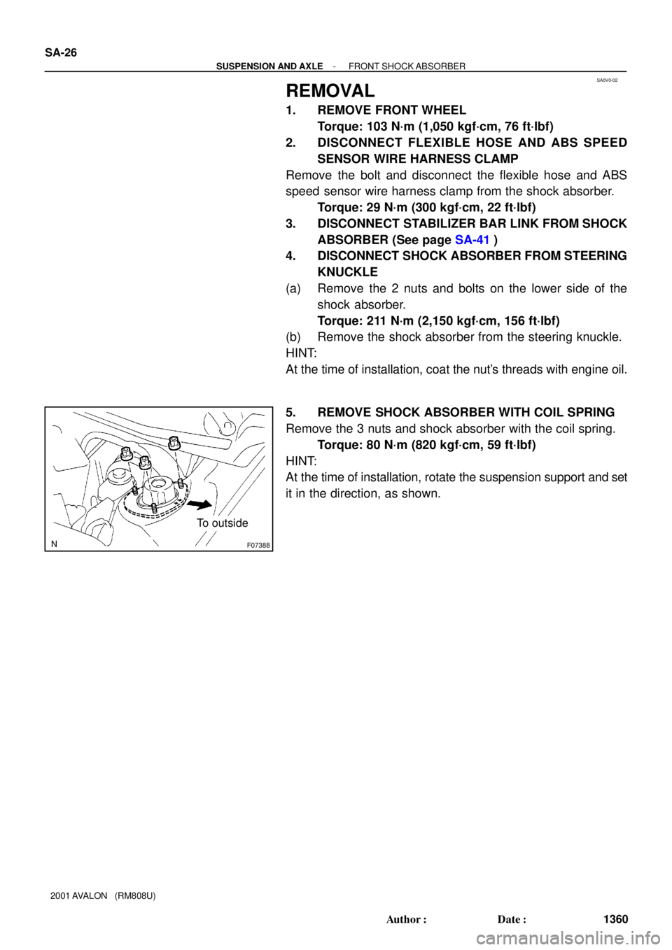
5. REMOVE SHOCK ABSORBER WITH COIL SPRING
Remove the 3 nuts and shock absorber with the coil spring.
Torque: 80 N´m (820 kgf´cm, 59 ft´lbf)
HINT:
At the time of installation, rotate the suspension support and set
it in the direction, as shown.
Page 1869 of 1897

F04031
F04048
1
2
F01195
Bolt
Adjusting
ValueSet Bolt
15'
30'Adjusting Bolt90105-17001 90105-17003 90105-17004 90105-17005
45'
1°00'
1°15'
1°30'121212121 Dot
2 Dots3 Dots
- SUSPENSION AND AXLEFRONT WHEEL ALIGNMENT
SA-5
1339 Author�: Date�:
2001 AVALON (RM808U)
4. ADJUST CAMBER
NOTICE:
After the camber has been adjusted, inspect the toe-in.
(a) Remove the front wheel and ABS speed sensor clamp.
(b) Remove the 2 nuts on the lower side of the shock absorb-
er.
(c) Coat the threads of the nuts with engine oil.
(d) Temporarily install the 2 nuts.
(e) Adjust the camber by pushing or pulling the lower side of
the shock absorber in the direction in which the camber
adjustment is required.
(f) Tighten the nuts.
Torque: 211 N´m (2,150 kgf´cm, 156 ft´lbf)
(g) Install the ABS speed sensor clamp and front wheel.
Torque: 103 N´m (1,050 kgf´cm, 76 ft´lbf)
(h) Check the camber.
HINT:
�Try to adjust the camber to the center of the specified val-
ue.
�Adjusting value for the set bolts is 6' - 30' (0.1° - 0.5°).
If the camber is not within the specified value, using the follow-
ing table, estimate how much additional camber adjustment will
be required, and select the camber adjusting bolt.
(i) Do the steps mentioned above again. Between step (b)
and (c), replace 1 or 2 selected bolts.
HINT:
When replacing the 2 bolts, replace 1 bolt for each time.
Page 1875 of 1897
R11165
SA-46
- SUSPENSION AND AXLEREAR AXLE HUB
1380 Author�: Date�:
2001 AVALON (RM808U)
HINT:
At the time of installation, please refer to the following items.
�After stabilizing the suspension, torque the nuts.
�If reusing the 2 nuts A, coat the nut's threads with engine
oil.
(b) Remove the bolt and nut, and disconnect the strut rod
from the rear axle carrier.
NOTICE:
Do not turn the nut.
Torque: 113 N´m (1,150 kgf´cm, 83 ft´lbf)
(c) Remove the 2 nuts and bolts on the lower side of the
shock absorber.
(d) Remove the nut, washer and bolt and disconnect the No.
1 and No. 2 lower suspension arm from the rear axle carri-
er.
(e) Remove the rear axle carrier.
Page 1888 of 1897

SA0WA-02
R00749
F01924
F07383
SA-50
- SUSPENSION AND AXLEREAR SHOCK ABSORBER
1384 Author�: Date�:
2001 AVALON (RM808U)
REMOVAL
1. REMOVE REAR SEAT (See page BO-1 19)
2. REMOVE REAR WHEEL
Torque: 103 N´m (1,050 kgf´cm, 76 ft´lbf)
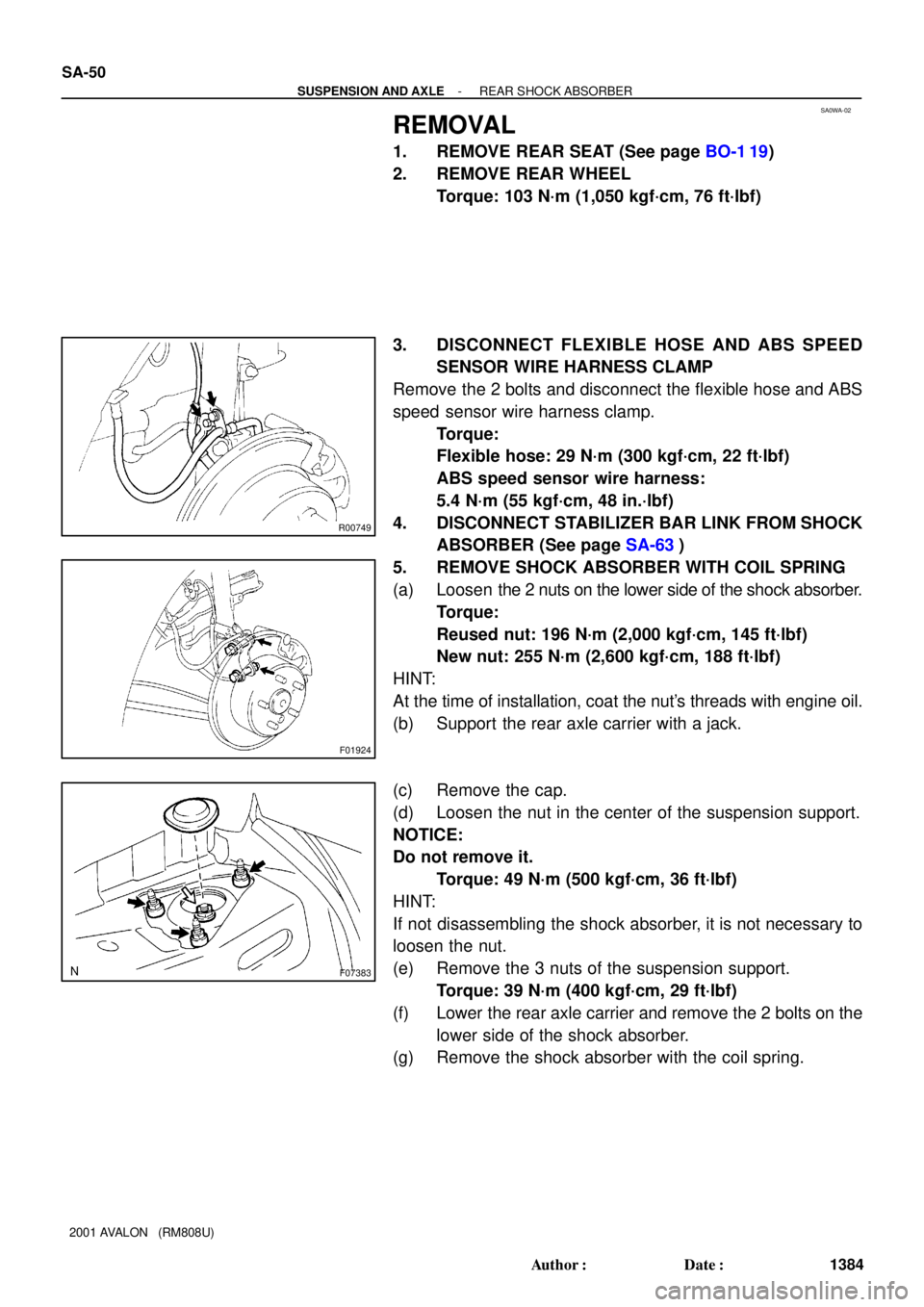
3. DISCONNECT FLEXIBLE HOSE AND ABS SPEED
SENSOR WIRE HARNESS CLAMP
Remove the 2 bolts and disconnect the flexible hose and ABS
speed sensor wire harness clamp.
Torque:
Flexible hose: 29 N´m (300 kgf´cm, 22 ft´lbf)
ABS speed sensor wire harness:
5.4 N´m (55 kgf´cm, 48 in.´lbf)
4. DISCONNECT STABILIZER BAR LINK FROM SHOCK
ABSORBER (See page SA-63)
5. REMOVE SHOCK ABSORBER WITH COIL SPRING
(a) Loosen the 2 nuts on the lower side of the shock absorber.
Torque:
Reused nut: 196 N´m (2,000 kgf´cm, 145 ft´lbf)
New nut: 255 N´m (2,600 kgf´cm, 188 ft´lbf)
HINT:
At the time of installation, coat the nut's threads with engine oil.
(b) Support the rear axle carrier with a jack.
(c) Remove the cap.
(d) Loosen the nut in the center of the suspension support.
NOTICE:
Do not remove it.
Torque: 49 N´m (500 kgf´cm, 36 ft´lbf)
HINT:
If not disassembling the shock absorber, it is not necessary to
loosen the nut.
(e) Remove the 3 nuts of the suspension support.
Torque: 39 N´m (400 kgf´cm, 29 ft´lbf)
(f) Lower the rear axle carrier and remove the 2 bolts on the
lower side of the shock absorber.
(g) Remove the shock absorber with the coil spring.