Page 542 of 1897
BR0L9-03
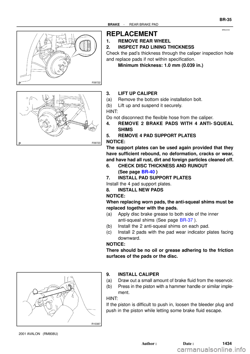
F09722
F09723
R10387
- BRAKEREAR BRAKE PAD
BR-35
1434 Author�: Date�:
2001 AVALON (RM808U)
REPLACEMENT
1. REMOVE REAR WHEEL
2. INSPECT PAD LINING THICKNESS
Check the pad's thickness through the caliper inspection hole
and replace pads if not within specification.
Minimum thickness: 1.0 mm (0.039 in.)
3. LIFT UP CALIPER
(a) Remove the bottom side installation bolt.
(b) Lift up and suspend it securely.
HINT:
Do not disconnect the flexible hose from the caliper.
4. REMOVE 2 BRAKE PADS WITH 4 ANTI- SQUEAL
SHIMS
5. REMOVE 4 PAD SUPPORT PLATES
NOTICE:
The support plates can be used again provided that they
have sufficient rebound, no deformation, cracks or wear,
and have had all rust, dirt and foreign particles cleaned off.
6. CHECK DISC THICKNESS AND RUNOUT
(See page BR-40)
7. INSTALL PAD SUPPORT PLATES
Install the 4 pad support plates.
8. INSTALL NEW PADS
NOTICE:
When replacing worn pads, the anti-squeal shims must be
replaced together with the pads.
(a) Apply disc brake grease to both side of the inner
anti-squeal shims (See page BR-37).
(b) Install the 2 anti-squeal shims on each pad.
(c) Install 2 pads with the pad wear indicator plates facing
downward.
NOTICE:
There should be no oil or grease adhering to the friction
surfaces of the pads or the disc.
9. INSTALL CALIPER
(a) Draw out a small amount of brake fluid from the reservoir.
(b) Press in the piston with a hammer handle or similar imple-
ment.
HINT:
If the piston is difficult to push in, loosen the bleeder plug and
push in the piston while letting some brake fluid escape.
Page 569 of 1897

CO02L-03
B09030Drain PlugDrain Plug
CO-2
- COOLINGCOOLANT
1195 Author�: Date�:
2001 AVALON (RM808U)
REPLACEMENT
1. DRAIN ENGINE COOLANT
(a) Remove the radiator cap from the water outlet.
CAUTION:
To avoid the danger of being burned, do not remove the ra-
diator cap while the engine and radiator are still hot, as fluid
and steam can be blown out under pressure.
(b) Loosen the radiator drain plug and engine drain plugs,
and drain the coolant.
(c) Close the drain plugs.
Torque:
RH engine drain plug on cylinder block side cover:
7 N´m (70 kgf´cm, 61 in.´lbf)
LH engine drain plug on union:
13 N´m (130 kgf´cm, 9 ft´lbf)
2. FILL ENGINE COOLANT
(a) Slowly fill the system with coolant.
�Use of improper coolants may damage engine cool-
ing system.
�Use ºToyota Long life Coolantº or equivalent and
mix it with plan water according to the manufactur-
er's directions.
�Using of coolant which includes more than 50 %
(freezing protection down to -35°C (-31°F) or 60 %
(freezing protection down to -50°C (-58°F)) of eth-
ylene-glycol is recommended but not more than 70
%.
NOTICE:
�Do not use an alcohol type coolant or plain water
alone.
�The coolant should be mixed with plain water (prefer-
ably demineralized water or distilled water).
Capacity: 9.0 liters (9.5 US qts, 7.9 lmp. qts)
(b) Install the radiator cap.
(c) Start the engine, and bleed the cooling system.
(d) If necessary, refill coolant into the reservoir up to the
ºFULLº line.
3. CHECK ENGINE COOLANT FOR LEAKS
4. CHECK ENGINE COOLANT SPECIFIC GRAVITY COR-
RECTLY
Page 578 of 1897
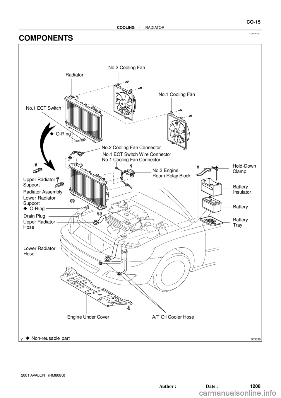
CO02W-03
B09039
Radiator
No.1 ECT Switch
No.2 Cooling Fan Connector
Upper Radiator
Support
Upper Radiator
HoseNo.1 Cooling Fan Connector
No.1 ECT Switch Wire Connector
Radiator Assembly
Lower Radiator
Support� O-Ring
A/T Oil Cooler Hose
No.3 Engine
Room Relay Block No.1 Cooling Fan
� Non-reusable part � O-Ring
Drain Plug
Lower Radiator
Hose
No.2 Cooling Fan
Battery
Insulator
Battery
Battery
Tray Hold-Down
Clamp
Engine Under Cover
- COOLINGRADIATOR
CO-15
1208 Author�: Date�:
2001 AVALON (RM808U)
COMPONENTS
Page 683 of 1897

F07902
PMCE2
- DIAGNOSTICSABS WITH EBD & BA & TRAC & VSC SYSTEM
DI-301
457 Author�: Date�:
2001 AVALON (RM808U)
INSPECTION PROCEDURE
HINT:
Start the inspection from step 1, in case of using the TOYOTA hand-held tester and start from step 2, in case
of not using the TOYOTA hand-held tester.
1 Check output value of the master cylinder pressure sensor.
PREPARATION:
(a) Connect the TOYOTA hand-held tester to the DLC3.
(b) Turn the ignition switch ON and push the TOYOTA hand-held tester main switch ON.
(c) Select the DATALIST mode on the TOYOTA hand-held tester.
CHECK:
Check that the brake fluid pressure value of the master cylinder pressure sensor displayed on the TOYOTA
hand-held tester is changing when depressing the brake pedal.
OK:
Brake fluid pressure value must be changing.
OK Go to step 4.
NG
2 Check master cylinder pressure sensor.
PREPARATION:
Install LSPV gauge to the front caliper bleeder plug portion, and
bleed the air from LSPV gauge.
SST 09709-29018
CHECK:
Start the engine and depress the brake pedal, then check the
relation between the fluid pressure and voltage of PMC and E2
terminals of the master cylinder pressure sensor with connector
still connected.
OK:
Front brake caliper fluid pressureVoltage
0 kPa (0 Kgf/cm2, 0 psi)0.44 - 0.76 V
5,883 kPa (60 kgf/cm2, 853 psi)1.34 - 1.66 V
11,768 kPa (120 kgf/cm2, 1,706 psi)2.24 - 2.56 V
HINT:
Voltage between terminals VCM and E2: 4.7 - 5.3 V
NG Replace master cylinder pressure sensor.
OK
Page 777 of 1897

AT3417
OK if hot
Add if hot
AT4657
AT8562
AT3417
OK if hot
Add if hot DI-166
- DIAGNOSTICSAUTOMATIC TRANSAXLE
322 Author�: Date�:
2001 AVALON (RM808U)
(3) Pull out the dipstick and wipe it clean.
(4) Push it back fully into the pipe.
(5) Pull it out and check that the fluid level is in the HOT
range.
If the level is not within the range, add new fluid.
Fluid type: ATF D-II or DEXRON®III (DEXRON®II)
NOTICE:
�Do not overfill.
�After filling ATF, check the oil level securely then
drive a vehicle.
(b) Check the fluid condition.
If the fluid smells burnt or is black, replace it.
(c) Replace the ATF.
(1) Remove the drain plug and drain the fluid.
(2) Reinstall the drain plug securely.
(3) With the engine OFF add new fluid through the oil
filler pipe.
Fluid type: ATF D-II or DEXRON®III (DEXRON®II)
Capacity: 4.75 liters (5.0 US qts, 4.2 Imp. qts)
(4) Start the engine and shift the shift lever into all posi-
tions from P to L position and then shift into P posi-
tion.
(5) With the engine idling, check the fluid level. Add
fluid up to the COOL level on the dipstick.
(6) Check the fluid level at the normal operating tem-
perature, 70 - 80 °C (158 - 176 °F), and add as
necessary.
NOTICE:
Do not overfill.
Page 778 of 1897

AT4252
0 - 1 mm (0 - 0.04 in.)
Q00199
D02450P N
R
- DIAGNOSTICSAUTOMATIC TRANSAXLE
DI-167
323 Author�: Date�:
2001 AVALON (RM808U)
(d) Check the fluid leaks.
Check for leaks in the transaxle.
If there are leaks, it is necessary to repair or replace O-rings,
gasket, oil seals, plugs or other parts.
(e) Inspect and adjust the throttle cable.
(1) Check that the accelerator pedal is fully released.
(2) Check that the inner cable is not slack.
(3) Measure the distance between the outer cable end
and stopper on the cable.
Standard distance: 0 - 1 mm (0 - 0.04 in.)
If the distance is not the standard, adjust the cable by adjusting
nuts.
(f) Inspect and adjust the shift lever position.
When shifting the shift lever from the N position to other
positions, check that the lever can be shifted smoothly
and accurately to each position and that the position indi-
cator is aligned with the correct position.
If the indicator is not aligned with the correct position, carry out
the following adjustment procedures.
(1) Loosen the nut on the shift lever.
(2) Push the control shaft fully downward.
(3) Return the control shaft lever 2 notches to N posi-
tion.
(4) Set the shift lever to N position.
(5) While holding the shift lever lightly toward the R
position side, tighten the shift lever nut.
Torque: 13 N´m (130 kgf´cm, 9 ft´lbf)
(6) Start the engine and make sure that the vehicle
moves forward when shifting the lever from the N to
D position and reverses when shifting it to the R
position.
Page 781 of 1897

DI-170
- DIAGNOSTICSAUTOMATIC TRANSAXLE
326 Author�: Date�:
2001 AVALON (RM808U)
7. HYDRAULIC TEST
Measure the line pressure.
NOTICE:
�Do the test at normal operation fluid temperature 50 - 80 °C (122 - 176 °F).
�The line pressure test should always be carried out in pairs. One technician should observe
the conditions of wheels or wheel stoppers outside the vehicle while the other is doing the test.
�Be careful to prevent SST's hose from interfering with the exhaust pipe.
(1) Warm up the ATF.
(2) Remove the test plug on the transaxle case front left side and connect SST (See page AX-33
for the location to connect SST).
SST 09992-00095 (09992-00231, 09992-00271)
(3) Fully apply the parking brake and chock the 4 wheels.
(4) Connect an OBD II scan tool or TOYOTA hand-held tester to DLC3.
(5) Start the engine and check idling speed.
(6) Keep your left foot pressing firmly on the brake pedal and shift into D position.
(7) Measure the line pressure when the engine is idling.
(8) Depress the accelerator pedal all the way down. Quickly read the highest line pressure when
engine speed reaches stall speed.
(9) In the same manner, do the test in R position.
Specified line pressure:
ConditionD position kPa (kgf/cm2, psi)R position kPa (kgf/cm2, psi)
Idling401 - 461 (4.1 - 4.7, 58 - 66)804 - 882 (8.2 - 9.0, 117 - 128)
Stall1,138 - 1,236 (11.6 - 12.6, 165 - 179)1,716 - 1,854 (17.5 - 18.9, 249 - 269)
If the measured pressure is not up to the specified value, recheck the throttle cable adjustment and retest.
Evaluation:
ProblemPossible cause
If the measured values at all positions are higher
�Throttle cable out of adjustment
�Throttle valve defective
�Regulator valve defective
If the measured values at all positions are lower
�Throttle cable out of adjustment
�Throttle valve defective
�Regulator valve defective
�Oil pump defective
�O/D direct clutch defective
If pressure is low in the D position only�D position circuit fluid leakage
�Forward clutch defective
If pressure is low in the R position only
�R position circuit fluid leakage
�Direct clutch defective
�1st & reverse brake defective
Page 810 of 1897
I13654
L9
Luggage Compartment
Light Switch
1
R-W12 12
4E 4C
RBody ECU
6
B4
LGC
2
L7
Luggage Compartment
Door Unlock MotorL4
IK1
L25
B4TR+ J/B No. 4
- DIAGNOSTICSBODY CONTROL SYSTEM
DI-649
805 Author�: Date�:
2001 AVALON (RM808U)
Luggage opener motor circuit
WIRING DIAGRAM
DI6LU-01