Page 1335 of 1897

EM0ZJ-02
A10520
A05218
12 Pointed Head Bolt
Front
7246
5318
7246
5318
A05223
Painted Mark
Front90°
- ENGINE MECHANICALCYLINDER HEAD
EM-59
1043 Author�: Date�:
2001 AVALON (RM808U)
INSTALLATION
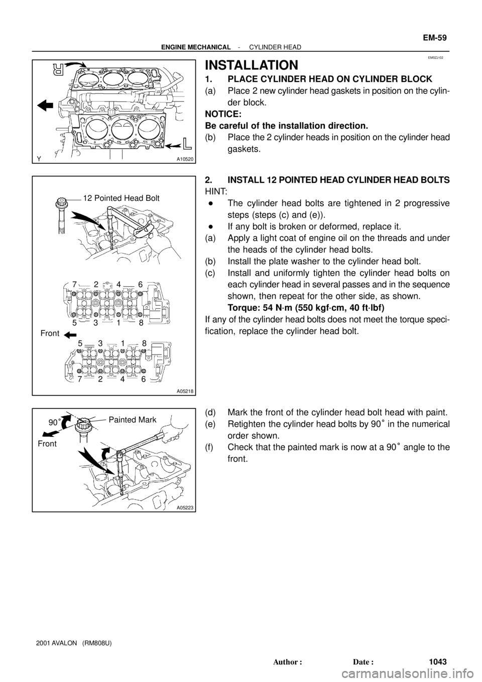
1. PLACE CYLINDER HEAD ON CYLINDER BLOCK
(a) Place 2 new cylinder head gaskets in position on the cylin-
der block.
NOTICE:
Be careful of the installation direction.
(b) Place the 2 cylinder heads in position on the cylinder head
gaskets.
2. INSTALL 12 POINTED HEAD CYLINDER HEAD BOLTS
HINT:
�The cylinder head bolts are tightened in 2 progressive
steps (steps (c) and (e)).
�If any bolt is broken or deformed, replace it.
(a) Apply a light coat of engine oil on the threads and under
the heads of the cylinder head bolts.
(b) Install the plate washer to the cylinder head bolt.
(c) Install and uniformly tighten the cylinder head bolts on
each cylinder head in several passes and in the sequence
shown, then repeat for the other side, as shown.
Torque: 54 N´m (550 kgf´cm, 40 ft´lbf)
If any of the cylinder head bolts does not meet the torque speci-
fication, replace the cylinder head bolt.
(d) Mark the front of the cylinder head bolt head with paint.
(e) Retighten the cylinder head bolts by 90° in the numerical
order shown.
(f) Check that the painted mark is now at a 90° angle to the
front.
Page 1336 of 1897
A05221
Recessed Head Bolt
Front8 mm Hexagon Wrench
P12595
Z09320
(3)
(2)
(1)
P12590
EM-60
- ENGINE MECHANICALCYLINDER HEAD
1044 Author�: Date�:
2001 AVALON (RM808U)
3. INSTALL RECESSED HEAD CYLINDER HEAD BOLTS
(a) Apply a light coat of engine oil on the threads and under
the heads of the cylinder head bolts.
(b) Using an 8 mm hexagon wrench, install the cylinder head
bolt on each cylinder head, then repeat for the other side,
as shown.
Torque: 18.5 N´m (185 kgf´cm, 13 ft´lbf)
4. ASSEMBLE EXHAUST CAMSHAFTS
(a) Mount the hexagonal wrench head portion of the cam-
shaft in a vise.
NOTICE:
Be careful not to damage the camshaft.
(b) Install the camshaft gear spring (1) and camshaft sub-
gear (2).
HINT:
Attach the pins on the gears to the gear spring ends.
(c) Install the wave washer (3).
(d) Using snap ring pliers, install the snap ring.
Page 1338 of 1897

A05283
Exhaust
A05202
Exhaust
7
A05203
Intake
Align
A05204
Intake
A05196
Intake
8
7
6
5
4
32
1
9
10
EM-62
- ENGINE MECHANICALCYLINDER HEAD
1046 Author�: Date�:
2001 AVALON (RM808U)
(b) Install the 5 bearing caps in their proper locations.
(c) Apply a light coat of engine oil on the threads and under
the heads of the bearing cap bolts.
(d) Install and uniformly tighten the 10 bearing cap bolts in
several passes and in the sequence shown.
Torque: 16 N´m (160 kgf´cm, 12 ft´lbf)
(e) Install the Intake camshaft.
(1) Apply new engine oil to the thrust portion and jour-
nal of the camshaft.
(2) Align the timing marks (2 dot marks) of the camshaft
drive and driven gears.
(3) Place the intake camshaft on the cylinder head.
(4) Install the 5 bearing caps in their proper locations.
(5) Apply a light coat of engine oil on the threads and
under the heads of the bearing cap bolts.
(6) Install and uniformly tighten the 10 bearing cap
bolts in several passes and in the sequence shown.
Torque: 16 N´m (160 kgf´cm, 12 ft´lbf)
Page 1340 of 1897

A05210
Exhaust
8
7
6
5
4
32
1
9
10
A05211
Intake
Align
A05214
Intake
A05213
Intake6
5
4
3
2
1
910
7
8
A05198
IntakeService Bolt
EM-64
- ENGINE MECHANICALCYLINDER HEAD
1048 Author�: Date�:
2001 AVALON (RM808U)
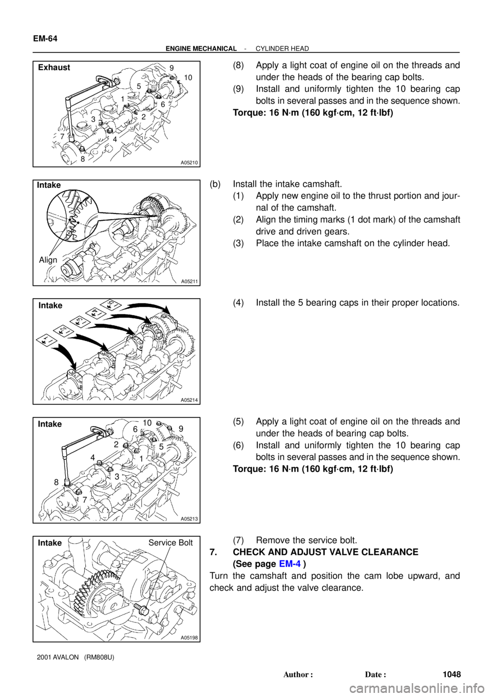
(8) Apply a light coat of engine oil on the threads and
under the heads of the bearing cap bolts.
(9) Install and uniformly tighten the 10 bearing cap
bolts in several passes and in the sequence shown.
Torque: 16 N´m (160 kgf´cm, 12 ft´lbf)
(b) Install the intake camshaft.
(1) Apply new engine oil to the thrust portion and jour-
nal of the camshaft.
(2) Align the timing marks (1 dot mark) of the camshaft
drive and driven gears.
(3) Place the intake camshaft on the cylinder head.
(4) Install the 5 bearing caps in their proper locations.
(5) Apply a light coat of engine oil on the threads and
under the heads of bearing cap bolts.
(6) Install and uniformly tighten the 10 bearing cap
bolts in several passes and in the sequence shown.
Torque: 16 N´m (160 kgf´cm, 12 ft´lbf)
(7) Remove the service bolt.
7. CHECK AND ADJUST VALVE CLEARANCE
(See page EM-4)
Turn the camshaft and position the cam lobe upward, and
check and adjust the valve clearance.
Page 1347 of 1897
A05276
P12719
SST
Z19062
Intake ExhaustMark
ºNOKº or
ºFN , INº
Light Brown SurfaceGray Surface
P12668
(4)
(3)
(2)
(1)
A05224
SST
- ENGINE MECHANICALCYLINDER HEAD
EM-57
1041 Author�: Date�:
2001 AVALON (RM808U)
4. INSTALL CYLINDER HEAD REAR COVER
Install the rear cover and gasket with the 6 bolts.
Torque: 10 N´m (100 kgf´cm, 7.3 ft´lbf)
5. INSTALL VALVES
(a) Using SST, push in a new oil seal.
SST 09201-41020
HINT:
The intake valve oil seal is light brown and the exhaust valve oil
seal is gray.
NOTICE:
Pay much attention when assembling the oil seal for intake
and exhaust. Assembling the wrong one may cause a fail-
ure.
(b) Install the valve (1), spring seat (2), valve spring (3) and
spring retainer (4).
(c) Using SST, compress the valve spring and place the 2
keepers around the valve stem.
SST 09202-70020 (09202-00010)
Page 1348 of 1897
A05246
EM-58
- ENGINE MECHANICALCYLINDER HEAD
1042 Author�: Date�:
2001 AVALON (RM808U)
(d) Using a plastic-faced hammer and the valve stem (not in
use) tip wound with vinyl tape, lightly tap the valve stem
tip to assure proper fit.
NOTICE:
Be careful not do damage the valve stem tip.
6. INSTALL VALVE LIFTERS AND SHIMS
(a) Install the valve lifter and shim.
(b) Check that the valve lifter rotates smoothly by hand.
Page 1359 of 1897

P12802
SST
Z09124
A05739
A05740
- ENGINE MECHANICALCYLINDER HEAD
EM-53
1037 Author�: Date�:
2001 AVALON (RM808U)
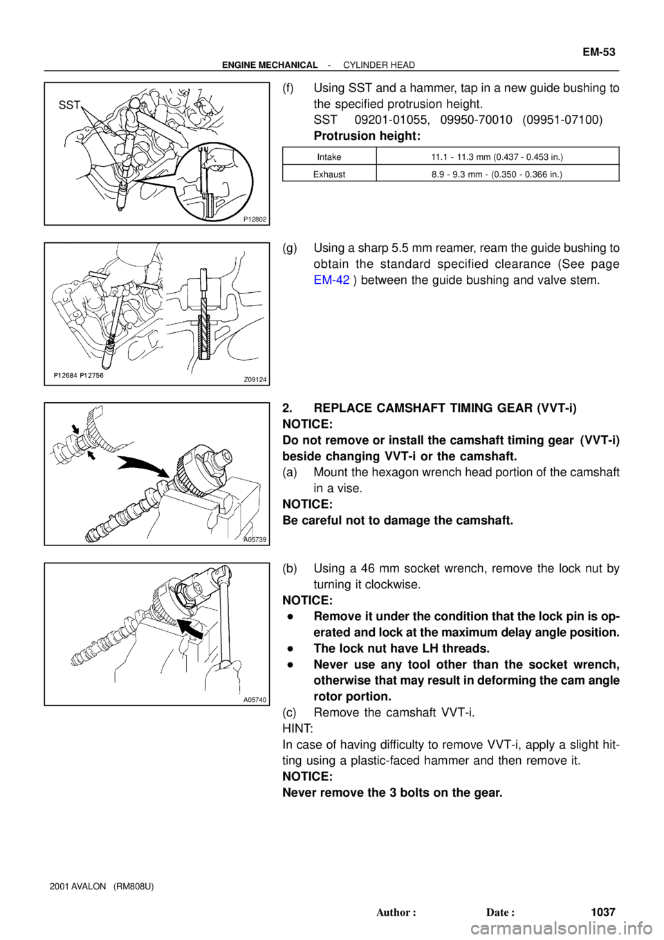
(f) Using SST and a hammer, tap in a new guide bushing to
the specified protrusion height.
SST 09201-01055, 09950-70010 (09951-07100)
Protrusion height:
Intake11.1 - 11.3 mm (0.437 - 0.453 in.)
Exhaust8.9 - 9.3 mm - (0.350 - 0.366 in.)
(g) Using a sharp 5.5 mm reamer, ream the guide bushing to
obtain the standard specified clearance (See page
EM-42) between the guide bushing and valve stem.
2. REPLACE CAMSHAFT TIMING GEAR (VVT-i)
NOTICE:
Do not remove or install the camshaft timing gear (VVT-i)
beside changing VVT-i or the camshaft.
(a) Mount the hexagon wrench head portion of the camshaft
in a vise.
NOTICE:
Be careful not to damage the camshaft.
(b) Using a 46 mm socket wrench, remove the lock nut by
turning it clockwise.
NOTICE:
�Remove it under the condition that the lock pin is op-
erated and lock at the maximum delay angle position.
�The lock nut have LH threads.
�Never use any tool other than the socket wrench,
otherwise that may result in deforming the cam angle
rotor portion.
(c) Remove the camshaft VVT-i.
HINT:
In case of having difficulty to remove VVT-i, apply a slight hit-
ting using a plastic-faced hammer and then remove it.
NOTICE:
Never remove the 3 bolts on the gear.
Page 1361 of 1897
A05244
SST
- ENGINE MECHANICALCYLINDER HEAD
EM-55
1039 Author�: Date�:
2001 AVALON (RM808U)
(d) Using SST and a hammer, tap in a new gasket until its sur-
face is flush with the upper edge of the cylinder head cov-
er.
SST 09608-03071
(e) Apply a light coat of MP grease to the gasket lip.
(f) Return the ventilation plate tab to its original position.