Page 1792 of 1897

5. INSTALL CYLINDER END STOPPER
(a) Align")
R11656
Cylinder
End StopperWire SST
R00662
SST
R11657
R11658
R11575
Vinyl Tape SR-50
- STEERINGPOWER STEERING GEAR
1513 Author�: Date�:
2001 AVALON (RM808U)
5. INSTALL CYLINDER END STOPPER
(a) Align the installation hole for the wire of the cylinder end
stopper with the slot of the rack housing.
(b) Install a new wire into the cylinder end stopper.
(c) Using SST, turn the cylinder end stopper clockwise 450
± 50°.
SST 09631-10021
6. AIR TIGHTNESS TEST
(a) Install SST to the rack housing.
SST 09631-12071
(b) Apply 53 kPa (400 mmHg, 15.75 in.Hg) of vacuum for
about 30 seconds.
(c) Check that there is no change in the vacuum.
If there is change in the vacuum, check the installation of the oil
seals.
7. INSTALL RACK HOUSING NO. 2 BRACKET AND
RACK HOSING NO. 2 GROMMET
(a) Install the rack housing No. 2 grommet to the rack housing
No. 2 bracket.
HINT:
Align the projection of the rack housing No. 2 grommet with the
hole of the rack housing No. 2 bracket.
(b) Align the matchmarks on the rack housing No. 2 bracket
and rack housing.
(c) Place the rack housing No. 2 bracket in a vise and install
the vise to fasten the clamp.
8. INSTALL CONTROL VALVE ASSEMBLY
(a) To prevent oil seal lip damage, wind vinyl tape on the ser-
rated part of the control valve shaft.
(b) Coat the teflon rings with power steering fluid.
(c) Install the control valve assembly into the control valve
housing.
NOTICE:
Be careful not to damage the teflon rings and oil seal.
Page 1793 of 1897

9. INSTALL OIL SEAL
(a) Coat a new oil seal lip with power steering fl")
W03562
Press
SST
Oil Seal
R11648
SST
R11659
Punch
- STEERINGPOWER STEERING GEAR
SR-51
1514 Author�: Date�:
2001 AVALON (RM808U)
9. INSTALL OIL SEAL
(a) Coat a new oil seal lip with power steering fluid.
(b) Using SST, press in the oil seal.
SST 09612-2201 1
NOTICE:
Make sure that the oil seal is installed facing in the correct
direction.
10. INSTALL CONTROL VALVE HOUSING WITH CON-
TROL VALVE ASSEMBLY
(a) Place a new gasket on the rack housing.
(b) Align the matchmarks on the control valve housing and
rack housing.
(c) Install the 2 bolts.
Torque: 18 N´m (180 kgf´cm, 13 ft´lbf)
11. INSTALL SELF-LOCKING NUT
Using SST, stop the control valve shaft rotating and install a new
self-locking nut.
SST 09616-0001 1
Torque: 25 N´m (250 kgf´cm, 18 ft´lbf)
12. INSTALL DUST SEAL
13. INSTALL RACK HOUSING CAP
(a) Apply sealant to 2 or 3 threads of the rack housing cap.
Sealant:
Part No.08833-00080, THREE BOND 1344,
LOCTITE 242 or equivalent
(b) Install the rack housing cap.
Torque: 59 N´m (600 kgf´cm, 43 ft´lbf)
(c) Using a punch and hammer, stake the 2 parts of the rack
housing cap.
14. INSTALL RACK GUIDE SUB- ASSEMBLY, RACK
GUIDE SPRING AND RACK GUIDE SPRING CAP
(a) Install the rack guide sub- assembly and rack guide
spring.
(b) Apply sealant to 2 or 3 threads of the rack guide spring
cap.
Sealant:
Part No.08833-00080, THREE BOND 1344,
LOCTITE 242 or equivalent
(c) Temporarily install the rack guide spring cap.
Page 1794 of 1897
W03098
SST Rack Guide
Spring Cap
W03099
12°
W03100
SST
W03101
SST
Rack Guide
Spring CapSST SR-52
- STEERINGPOWER STEERING GEAR
1515 Author�: Date�:
2001 AVALON (RM808U)
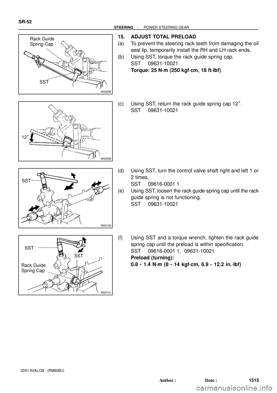
15. ADJUST TOTAL PRELOAD
(a) To prevent the steering rack teeth from damaging the oil
seal lip, temporarily install the RH and LH rack ends.
(b) Using SST, torque the rack guide spring cap.
SST 09631-10021
Torque: 25 N´m (250 kgf´cm, 18 ft´lbf)
(c) Using SST, return the rack guide spring cap 12°.
SST 09631-10021
(d) Using SST, turn the control valve shaft right and left 1 or
2 times.
SST 09616-0001 1
(e) Using SST, loosen the rack guide spring cap until the rack
guide spring is not functioning.
SST 09631-10021
(f) Using SST and a torque wrench, tighten the rack guide
spring cap until the preload is within specification.
SST 09616-0001 1, 09631-10021
Preload (turning):
0.8 - 1.4 N´m (8 - 14 kgf´cm, 6.9 - 12.2 in.´lbf)
Page 1799 of 1897

SR0RX-02
F01792
Press
SST
Oil Seal
Bearing
W03560
Press
SST
Oil SealSST
F03877
PressSST
SST Bearing
F01794
Brass Bar
Bearing
F01795
Press
SST
Bearing
SR-46
- STEERINGPOWER STEERING GEAR
1509 Author�: Date�:
2001 AVALON (RM808U)
REPLACEMENT
NOTICE:
When using a vise, do not over tighten it.
1. IF NECESSARY, REPLACE OIL SEAL AND BEARING
(a) Using SST, press out the oil seal and bearing from the
control valve housing.
SST 09950-60010 (09951-00250),
09950-70010 (09951-07200)
(b) Coat a new oil seal lip with power steering fluid.
(c) Using SST, press in the oil seal.
SST 09950-60010 (09951-00180, 09951-00320,
09952-06010), 09950-70010 (09951-07200)
NOTICE:
Make sure that the oil seal is installed facing in the correct
direction.
(d) Coat a new bearing with molybdenum disulfide lithium
base grease.
(e) Using SST, press in the bearing.
SST 09950-60010 (09951-00180, 09951-00340,
09952-06010), 09950-70010 (09951-07200)
2. IF NECESSARY, REPLACE 2 BEARINGS
(a) Using a brass bar and hammer, tap out the bearing from
the rack housing.
(b) Using SST, press out the bearing from the rack housing.
SST 09950-60010 (09951-00260),
09950-70010 (09951-07200)
Page 1800 of 1897
")
F03878
PressSST
SST
Bearing
F01797
Press
SST
Bearing
F01798SST
BushingOil
Seal
SST
F03863
Press
Oil Seal
SST
SST
R10955
- STEERINGPOWER STEERING GEAR
SR-47
1510 Author�: Date�:
2001 AVALON (RM808U)
(c) Coat a new bearing with molybdenum disulfide lithium
base grease.
(d) Using SST, press in the bearing.
SST 09950-60010 (09951-00250, 09951-00310,
09952-06010), 09950-70010 (09951-07200)
(e) Coat a new bearing with molybdenum disulfide lithium
base grease.
(f) Using SST, press in the bearing.
SST 09950-60010 (09951-00320),
09950-70010 (09951-07200)
3. IF NECESSARY, REPLACE OIL SEAL
(a) Using SST, remove the oil seal from the bushing.
SST 09527-2001 1, 09612-24014 (09613-22011)
NOTICE:
Be careful not to damage the bushing.
(b) Coat a new oil seal lip with power steering fluid.
(c) Using SST, press in the oil seal.
SST 09950-60010 (09951-00240, 09951-00400,
09952-06010)
NOTICE:
Make sure that the oil seal is installed facing in the correct
direction.
4. IF NECESSARY, REPLACE TEFLON RING AND O-
RING
(a) Using a screwdriver, remove the teflon ring and O-ring
from the steering rack.
NOTICE:
Be careful not to damage the groove for the teflon ring.
(b) Coat a new O-ring with power steering fluid and install it.
Page 1802 of 1897
SR0EN-06
F08851
Connector
Oil Pressure Switch
Union Bolt
� Gasket
Return HoseDrive Belt
Clamp Plate
Pressure Feed Tube
Pressure Feed Tube
PS Vane Pump AssemblyHolder
Clamp Plate
Clamp Plate
Front Fender Apron Seal RH
� Non-reusable part
43 (440, 32)
*29 (300, 22)
7.8 (80, 69 in.´lbf)
21 (210, 15)
52 (530, 38)
43 (440, 32)
25 (250, 18)
*22 (230, 17)
N´m (kgf´cm, ft´lbf): Specified torque
* For use with SST
- STEERINGPOWER STEERING VANE PUMP
SR-25
1488 Author�: Date�:
2001 AVALON (RM808U)
POWER STEERING VANE PUMP
COMPONENTS
Page 1803 of 1897
F08852
Pressure Port Union
� O-Ring
Flow Control Valve
Suction Port Union
SpringRear Housing
Rear
Bracket
Front Housing
Front Bracket
Vane Pump Shaft
Vane Pump PulleyVane Pump
Rotor
� Straight Pin
Wave Washer � O-Ring� O-Ring
� Gasket
Side Plate
Cam Ring
Vane Platex 10
� Oil Seal�
� Snap Ring
� Non-reusable part
Power steering fluid
83 (850, 62)
13 (130, 9)
43 (440, 32)
43 (440, 32)
17 (170, 12)
17 (170, 12)
44 (450, 33)
N´m (kgf´cm, ft´lbf): Specified torque
SR-26
- STEERINGPOWER STEERING VANE PUMP
1489 Author�: Date�:
2001 AVALON (RM808U)
Page 1805 of 1897
SR0RT-02
R15196
Caliper Gauge
Micrometer
Vane Pump Shaft
Bushing
Front Housing
N00372
Thickness
Length Height
R10282
Feeler Gauge
- STEERINGPOWER STEERING VANE PUMP
SR-29
1492 Author�: Date�:
2001 AVALON (RM808U)
INSPECTION
NOTICE:
When using a vise, do not overtighten it.
1. MEASURE OIL CLEARANCE BETWEEN VANE PUMP
SHAFT AND BUSHING
Using a micrometer and caliper gauge, measure the oil clear-
ance.
Standard clearance:
0.03 - 0.05 mm (0.0012 - 0.0020 in.)
Maximum clearance: 0.07 mm (0.0028 in.)
If it is more than the maximum, replace the front housing and
vane pump shaft.
2. INSPECT VANE PUMP ROTOR AND VANE PLATES
(a) Using a micrometer, measure the height, thickness and
length of the vane plates.
Minimum height: 8.6 mm (0.339 in.)
Minimum thickness: 1.397 mm (0.0550 in.)
Minimum length: 14.991 mm (0.5902 in.)
(b) Using a feeler gauge, measure the clearance between
the vane pump rotor groove and vane plate.
Maximum clearance: 0.035 mm (0.0014 in.)