Page 1648 of 1897

S05054
New Gasket
FI1654
Fulcrum Length
30 cm
SST
FI6372
CORRECT New O-Ring
Delivery Pipe
Injector Grommet
WRONG
B05295
O-Ring
Grommet
Spacer InsulatorDelivery Pipe
O-Ring
- SFISFI SYSTEM
SF-3
111 2 Author�: Date�:
2001 AVALON (RM808U)
(b) When connecting the union bolt on the high pressure pipe
union, observe the following procedures:
(1) Always use 2 new gaskets.
(2) Tighten the union bolt by hand.
(3) Tighten the union bolt to the specified torque.
Torque: 29 N´m (300 kgf´cm, 21 ft´lbf)
(c) When connecting the flare nut on the high pressure pipe
union, observe the following procedures:
(1) Apply a light coat of engine oil to the flare nut, and
tighten the flare nut by hand.
(2) Using SST, tighten the flare nut to specified torque.
SST 09023-12700
NOTICE:
Do not rotate the fuel pipe, when tightening the flare nut.
Torque: 28 N´m (285 kgf´cm, 21 ft´lbf)
HINT:
Use a torque wrench with a fulcrum length of 30 cm (11.81 in.).
(d) Observe the following precautions when removing and
installing the injectors.
(1) Never reuse the O-ring.
(2) When placing a new O-ring on the injector, take
care not to damage it in any way.
(3) Coat a new O-ring with spindle oil or gasoline be-
fore installing-never use engine, gear or brake oil.
(e) Install the injector to the delivery pipe and intake manifold
as shown in the illustration.
(f) Observe these precautions when disconnecting the fuel
tube connector (quick type).
(1) Check if there is any dirt like mud on the pipe and
around the connector before disconnecting them
and clean the dirt away.
(2) Be sure to disconnect with hands.
Page 1649 of 1897

S04583
S05040
Vinyl Bag
S05382
Retainer
S05050
Click Sound SF-4
- SFISFI SYSTEM
111 3 Author�: Date�:
2001 AVALON (RM808U)
(3) When the connector and the pipe are stuck, pinch
the retainer between the hands, push and pull the
connector to free to disconnect and pull it out. Do
not use any tool at this time.
(4) Inspect if there is any dirt or the likes on the seal sur-
face of the disconnected pipe and clean it away.
(5) Prevent the disconnected pipe and connector from
damaging and mixing foreign objects by covering
them with a vinyl bag.
(g) Observe these precautions when connecting the fuel
tube connector (quick type).
(1) Do not reuse the retainer removed from the pipe.
(2) Must use hands without using tools when to remove
the retainer from the pipe.
(3) Check if there is any damage or foreign objects on
the connected part of the pipe.
(4) Match the axis of the connector with axis of the pipe,
and push in the connector until the retainer makes
a ºclickº sound. In case that the connections is tight,
apply little amount of new engine oil on the tip of the
pipe.
(5) After having finished the connection, check if the
pipe and the connector are securely connected by
pulling them.
(6) Check if there is any fuel leakage.
(h) Observe these precautions when handling nylon tube.
(1) Pay attention not to turn the connector with force
when connecting them.
(2) Pay attention not to kink the nylon tube.
(3) Do not remove the EPDM protector on the outside
of the nylon tube.
(4) Must not close the piping with the nylon tube by
bending it.
Before installing the injector, must apply spindle oil
or gasoline on the place where a delivery pipe or an
intake manifold touches an O-ring of the injector.
Page 1757 of 1897
B01154
� Snap Ring
Starter Housing
Starter Clutch
Compression Spring
Clutch Shaft
Starter Housing and
Clutch Assembly
Idler Gear
Bearing Stop Collar
Pinion Gear
Compression Spring
Spring Retainer
Steel Ball
Return
Spring
� Front Bearing
Armature
� O-Ring
Field Frame
(Field Coil)
End Cover Brush Holder � Rear Bearing
� Dust Protector
� Non-reusable part
Magnetic Switch
Assembly
� O-Ring
- STARTINGSTARTER
ST-3
1256 Author�: Date�:
2001 AVALON (RM808U)
Page 1761 of 1897

P10584
Ohmmeter
Continuity
ST04Q-02
P10585
Ohmmeter
No Continuity
P10586
P10587
ST0040
ST-8
- STARTINGSTARTER
1261 Author�: Date�:
2001 AVALON (RM808U)
INSPECTION
1. INSPECT ARMATURE COIL
(a) Check the commutator for open circuit.
Using an ohmmeter, check that there is continuity be-
tween the segments of the commutator.
If there is no continuity between any segment, replace the ar-
mature.
(b) Check the commutator for ground
Using an ohmmeter, check that there is no continuity be-
tween the commutator and armature coil core.
If there is continuity, replace the armature.
2. INSPECT COMMUTATOR
(a) Check the commutator for dirty and burnt surfaces.
If the surface is dirty or burnt, correct it with sandpaper (No.400)
or on a lathe.
(b) Check the commutator circle runout.
(1) Place the commutator on V-blocks.
(2) Using a dial gauge, measure the circle runout.
Maximum circle runout: 0.05 mm (0.0020 in.)
If the circle runout is greater than maximum, correct it on a lathe.
(c) Using vernier calipers, measure the commutator diame-
ter.
Standard diameter: 30.0 mm (1.181 in.)
Minimum diameter: 29.0 mm (1.142 in.)
If the diameter is less than minimum, replace the armature.
(d) Check that the undercut depth is clean and free of foreign
materials. Smooth out the edge.
Standard undercut depth: 0.6 mm (0.024 in.)
Minimum undercut depth: 0.2 mm (0.008 in.)
If the undercut depth is less than minimum, correct it with a
hacksaw blade.
Page 1762 of 1897

P10588
Ohmmeter
Continuity
P10589
Ohmmeter
No Continuity
Z10079
Brush Holder Side
Field Flame Side Length
Length
ST0019
- STARTINGSTARTER
ST-9
1262 Author�: Date�:
2001 AVALON (RM808U)
3. INSPECT FIELD COIL
(a) Check the field coil for open circuit.
Using an ohmmeter, check that there is continuity be-
tween the lead wire and field coil brush lead.
If there is no continuity, replace the field frame.
(b) Check the field coil for ground.
Using an ohmmeter, check that there is no continuity be-
tween the field coil end and field frame.
If there is continuity, repair or replace the field frame.
4. INSPECT BRUSHES
Using vernier calipers, measure the brush length.
Standard length: 15.5 mm (0.610 in.)
Minimum length: 10 mm (0.394 in.)
If the length is less than minimum, replace the brush holder and
field frame.
5. INSPECT BRUSH SPRINGS
Check the brush spring road.
Take the pull scale reading the instant the brush spring
separates from the brush.
Standard spring installed load:
17.6 - 23.5 N (1.79 - 2.41 kgf, 4.0 - 5.3 lbf)
Minimum spring installed load:
11.8 N (1.20 kgf, 2.7 lbf)
If the installed load is less than minimum replace the brush
springs.
Page 1763 of 1897

P13481
Ohmmeter
No Continuity
B01162
Lock
Free
B01163
Terminal C
Terminal 50Ohmmeter
Continuity
B01164Terminal 50Ohmmeter
Continuity
ST-10
- STARTINGSTARTER
1263 Author�: Date�:
2001 AVALON (RM808U)
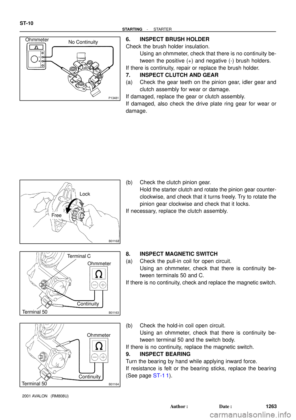
6. INSPECT BRUSH HOLDER
Check the brush holder insulation.
Using an ohmmeter, check that there is no continuity be-
tween the positive (+) and negative (-) brush holders.
If there is continuity, repair or replace the brush holder.
7. INSPECT CLUTCH AND GEAR
(a) Check the gear teeth on the pinion gear, idler gear and
clutch assembly for wear or damage.
If damaged, replace the gear or clutch assembly.
If damaged, also check the drive plate ring gear for wear or
damage.
(b) Check the clutch pinion gear.
Hold the starter clutch and rotate the pinion gear counter-
clockwise, and check that it turns freely. Try to rotate the
pinion gear clockwise and check that it locks.
If necessary, replace the clutch assembly.
8. INSPECT MAGNETIC SWITCH
(a) Check the pull-in coil for open circuit.
Using an ohmmeter, check that there is continuity be-
tween terminals 50 and C.
If there is no continuity, check and replace the magnetic switch.
(b) Check the hold-in coil open circuit.
Using an ohmmeter, check that there is continuity be-
tween terminal 50 and the switch body.
If there is no continuity, replace the magnetic switch.
9. INSPECT BEARING
Turn the bearing by hand while applying inward force.
If resistance is felt or the bearing sticks, replace the bearing
(See page ST-1 1).
Page 1772 of 1897
B01240
SST
B01241
ST-16
- STARTINGSTARTER
1269 Author�: Date�:
2001 AVALON (RM808U)
�If the contact plate is not pressed down with the spe-
cified pressure, the contact plate may tilt due to coil
deformation or the tightening of the nut.
(2) Using SST, tighten the nuts to the specified torque.
SST 09810-38140
Torque: 17 N´m (173 kgf´cm, 12 ft´lbf)
NOTICE:
If the nut is over tightened, it may cause cracks on the in-
side of the insulator.
(g) Clean the contact surfaces of the remaining contact plate
and plunger with a dry shop rag.
(h) Install the plunger, new gasket, end cover and 3 bolts.
Torque: 2.5 N´m (25 kgf´cm, 22 in.´lbf)
Page 1773 of 1897

ST04T-02
B01242
Terminal C
Battery
Terminal 50
B01243
Terminal C
BatteryDisconnect
B01244Battery
Disconnect
B01245
Battery
Terminal 50
Terminal 30
Ammeter
ST-18
- STARTINGSTARTER
1271 Author�: Date�:
2001 AVALON (RM808U)
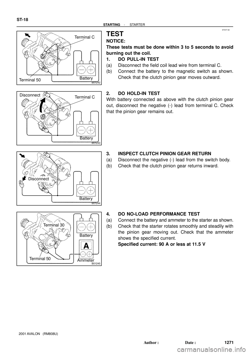
TEST
NOTICE:
These tests must be done within 3 to 5 seconds to avoid
burning out the coil.
1. DO PULL-IN TEST
(a) Disconnect the field coil lead wire from terminal C.
(b) Connect the battery to the magnetic switch as shown.
Check that the clutch pinion gear moves outward.
2. DO HOLD-IN TEST
With battery connected as above with the clutch pinion gear
out, disconnect the negative (-) lead from terminal C. Check
that the pinion gear remains out.
3. INSPECT CLUTCH PINION GEAR RETURN
(a) Disconnect the negative (-) lead from the switch body.
(b) Check that the clutch pinion gear returns inward.
4. DO NO-LOAD PERFORMANCE TEST
(a) Connect the battery and ammeter to the starter as shown.
(b) Check that the starter rotates smoothly and steadily with
the pinion gear moving out. Check that the ammeter
shows the specified current.
Specified current: 90 A or less at 11.5 V