Page 1837 of 1897

REMOVAL
1. REMOVE FRONT WHEEL
Torque: 103 N´m (1,050 kgf´cm, 76 ft´lbf)
2. CHECK")
SA0VS-02
W03084
W03093
W03139
- SUSPENSION AND AXLEFRONT AXLE HUB
SA-9
1343 Author�: Date�:
2001 AVALON (RM808U)
REMOVAL
1. REMOVE FRONT WHEEL
Torque: 103 N´m (1,050 kgf´cm, 76 ft´lbf)
2. CHECK BEARING BACKLASH AND AXLE HUB DEVI-
ATION
(a) Remove the 2 bolts, brake caliper and disc.
(b) Support the brake caliper securely.
(c) Using a dial indicator, check the backlash near the center
of the axle hub.
Maximum: 0.05 mm (0.0020 in.)
If the backlash exceeds the maximum, replace the bearing.
(d) Using a dial indicator, check the deviation at the surface
of the axle hub outside the hub bolt.
Maximum: 0.05 mm (0.0020 in.)
If the deviation exceeds the maximum, replace the axle hub.
(e) Install the disc, brake caliper and 2 bolts.
Torque: 107 N´m (1,090 kgf´cm, 79 ft´lbf)
3. REMOVE DRIVE SHAFT LOCK NUT
(a) Remove the cotter pin and lock cap.
(b) While applying the brakes, remove the nut.
Torque: 294 N´m (3,000 kgf´cm, 217 ft´lbf)
(c) Remove the 2 bolts, brake caliper and disc.
(d) Support the brake caliper securely.
4. DISCONNECT ABS SPEED SENSOR AND WIRE HAR-
NESS CLAMP
Remove the bolt and disconnect the ABS speed sensor and
wire harness clamp.
Torque: 8.0 N´m (82 kgf´cm, 71 in.´lbf)
5. LOOSEN 2 NUTS ON LOWER SIDE OF SHOCK AB-
SORBER
HINT:
Do not remove the bolts.
Torque: 211 N´m (2,150 kgf´cm, 156 ft´lbf)
HINT:
At the this time of installation, coat the nut's thread with engine
oil.
Page 1847 of 1897

REMOVAL
NOTICE:
�The hub bearing could be damaged if it is subjected
t")
SA0VY-02
FA1535
SST
W03093
W03142
F07389
SA-16
- SUSPENSION AND AXLEFRONT DRIVE SHAFT
1350 Author�: Date�:
2001 AVALON (RM808U)
REMOVAL
NOTICE:
�The hub bearing could be damaged if it is subjected
to the vehicle weight, such as when moving the ve-
hicle with the drive shaft removed.
Therefore, if it is absolutely necessary to place the ve-
hicle weight on the hub bearing, first support it with
SST.
SST 09608-16042 (09608-02021, 09608-02041)
�After disconnecting the drive shaft from the axle hub,
work carefully so as not to damage the ABS speed
sensor rotor serration on the drive shaft.
1. REMOVE FRONT WHEEL
Torque: 103 N´m (1,050 kgf´cm, 76 ft´lbf)
2. REMOVE FRONT FENDER APRON SEAL
3. DRAIN ATF
4. REMOVE DRIVE SHAFT LOCK NUT
(a) Remove the cotter pin and lock cap.
(b) While applying brakes, remove the nut.
Torque: 294 N´m (3,000 kgf´cm, 217 ft´lbf)
5. DISCONNECT TIE ROD END FROM STEERING
KNUCKLE (See page SA-9)
6. DISCONNECT LOWER SUSPENSION ARM FROM
LOWER BALL JOINT (See page SA-9)
7. DISCONNECT DRIVE SHAFT FROM AXLE HUB
Using a plastic hammer, disconnect the drive shaft from the axle
hub.
NOTICE:
Be careful not to damage the boot and ABS speed sensor
rotor.
8. LH drive shaft:
REMOVE DRIVE SHAFT
(a) Using a hub nut wrench and hammer handle or an equiva-
lent, remove the drive shaft.
NOTICE:
Be careful not to damage the dust cover and oil seal.
Page 1848 of 1897

HINT:
At the time of installation, please refer to the following items.
�Coat gear oil to the inboard jo")
W03144
- SUSPENSION AND AXLEFRONT DRIVE SHAFT
SA-17
1351 Author�: Date�:
2001 AVALON (RM808U)
HINT:
At the time of installation, please refer to the following items.
�Coat gear oil to the inboard joint shaft and differential
case sliding surface.
�Before installing the drive shaft, set the snap ring opening
side facing downward.
�Whether or not the inboard joint shaft is making contact
with the pinion shaft can be known by the sound or feeling
when driving it in.
�After installation, check that there is 2 - 3 mm (0.08 - 0.12
in.) of play in the axial direction.
�After installation, check that the drive shaft cannot be re-
moved by hand.
(b) Using a screwdriver, remove the snap ring from the in-
board joint shaft.
9. RH drive shaft:
REMOVE DRIVE SHAFT
(a) Remove the bearing lock bolt.
Torque: 32 N´m (330 kgf´cm, 24 ft´lbf)
(b) Using pliers, remove the snap ring and drive shaft.
NOTICE:
Be careful not to damage the dust cover and oil seal.
HINT:
At the time of installation, coat gear oil to the inboard joint shaft
and differential case sliding surface.
Page 1857 of 1897
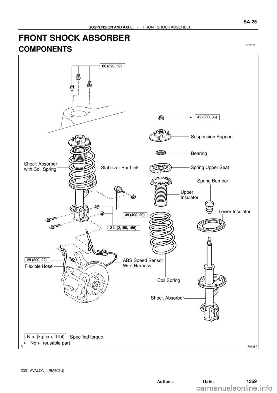
SA0UZ-02
F07387
N´m (kgf´cm, ft´lbf)
: Specified torque
Non- reusable part
�
80 (820, 59)
39 (400, 29)
211 (2,150, 156)
29 (300, 22)
Flexible HoseABS Speed Sensor
Wire Harness
Coil Spring
Shock AbsorberLower Insulator Upper
InsulatorSpring Bumper Spring Upper SeatBearing Suspension Support �
Stabilizer Bar Link Shock Absorber
with Coil Spring
49 (500, 36)
- SUSPENSION AND AXLEFRONT SHOCK ABSORBER
SA-25
1359 Author�: Date�:
2001 AVALON (RM808U)
FRONT SHOCK ABSORBER
COMPONENTS
Page 1858 of 1897
SA0V1-02
W03198
SST
SST
W03199
SST
- SUSPENSION AND AXLEFRONT SHOCK ABSORBER
SA-27
1361 Author�: Date�:
2001 AVALON (RM808U)
DISASSEMBLY
REMOVE COIL SPRING
(a) Install 2 nuts and a bolt to the bracket at the lower side of
the shock absorber and secure it in a vise.
(b) Using 2 SST of the same type, compress the coil spring.
SST 09727-30021
NOTICE:
Do not use an impact wrench. It will damage the SST.
(c) Using SST to hold the suspension support, remove the
nut.
SST 09729-22031
(d) Remove the suspension support, bearing, spring upper
seat, upper insulator, coil spring, lower insulator and
spring bumper.
Page 1862 of 1897

REASSEMBLY
1. INSTALL LOWER INSULATOR ONTO SHOCK AB-
SORBER
2. INSTALL")
SA0V4-02
W03200
SST
W03201
W03199
SST SA-30
- SUSPENSION AND AXLEFRONT SHOCK ABSORBER
1364 Author�: Date�:
2001 AVALON (RM808U)
REASSEMBLY
1. INSTALL LOWER INSULATOR ONTO SHOCK AB-
SORBER
2. INSTALL SPRING BUMPER TO PISTON ROD
3. INSTALL COIL SPRING
(a) Using 2 SST of the same type, compress the coil spring.
SST 09727-30021
NOTICE:
Do not use an impact wrench. It will damage the SST.
(b) Install the coil spring to the shock absorber.
HINT:
Fit the lower end of the coil spring into the gap of the spring low-
er seat.
4. INSTALL SPRING UPPER SEAT AND INSULATOR
(a) Align the 'OUT' mark of spring upper seat with the mark
of the upper insulator.
(b) Install the spring upper seat with upper insulator to the
shock absorber with the mark facing to the outside of the
vehicle.
(c) Install the bearing and suspension support.
(d) Using SST to hold the suspension support, install a new
nut.
SST 09729-22031
Torque: 49 N´m (500 kgf´cm, 36 ft´lbf)
(e) Remove the 2 SST from the coil spring.
NOTICE:
Check that the bearing fits into the recess in the suspen-
sion support.
Page 1863 of 1897

REMOVAL
1. REMOVE FRONT WHEEL
Torque: 103 N´m (1,050 kgf´cm, 76 ft´lbf)
2. DIS")
SA0V0-02
F07388
To outside SA-26
- SUSPENSION AND AXLEFRONT SHOCK ABSORBER
1360 Author�: Date�:
2001 AVALON (RM808U)
REMOVAL
1. REMOVE FRONT WHEEL
Torque: 103 N´m (1,050 kgf´cm, 76 ft´lbf)
2. DISCONNECT FLEXIBLE HOSE AND ABS SPEED
SENSOR WIRE HARNESS CLAMP
Remove the bolt and disconnect the flexible hose and ABS
speed sensor wire harness clamp from the shock absorber.
Torque: 29 N´m (300 kgf´cm, 22 ft´lbf)
3. DISCONNECT STABILIZER BAR LINK FROM SHOCK
ABSORBER (See page SA-41)
4. DISCONNECT SHOCK ABSORBER FROM STEERING
KNUCKLE
(a) Remove the 2 nuts and bolts on the lower side of the
shock absorber.
Torque: 211 N´m (2,150 kgf´cm, 156 ft´lbf)
(b) Remove the shock absorber from the steering knuckle.
HINT:
At the time of installation, coat the nut's threads with engine oil.
5. REMOVE SHOCK ABSORBER WITH COIL SPRING
Remove the 3 nuts and shock absorber with the coil spring.
Torque: 80 N´m (820 kgf´cm, 59 ft´lbf)
HINT:
At the time of installation, rotate the suspension support and set
it in the direction, as shown.
Page 1869 of 1897

F04031
F04048
1
2
F01195
Bolt
Adjusting
ValueSet Bolt
15'
30'Adjusting Bolt90105-17001 90105-17003 90105-17004 90105-17005
45'
1°00'
1°15'
1°30'121212121 Dot
2 Dots3 Dots
- SUSPENSION AND AXLEFRONT WHEEL ALIGNMENT
SA-5
1339 Author�: Date�:
2001 AVALON (RM808U)
4. ADJUST CAMBER
NOTICE:
After the camber has been adjusted, inspect the toe-in.
(a) Remove the front wheel and ABS speed sensor clamp.
(b) Remove the 2 nuts on the lower side of the shock absorb-
er.
(c) Coat the threads of the nuts with engine oil.
(d) Temporarily install the 2 nuts.
(e) Adjust the camber by pushing or pulling the lower side of
the shock absorber in the direction in which the camber
adjustment is required.
(f) Tighten the nuts.
Torque: 211 N´m (2,150 kgf´cm, 156 ft´lbf)
(g) Install the ABS speed sensor clamp and front wheel.
Torque: 103 N´m (1,050 kgf´cm, 76 ft´lbf)
(h) Check the camber.
HINT:
�Try to adjust the camber to the center of the specified val-
ue.
�Adjusting value for the set bolts is 6' - 30' (0.1° - 0.5°).
If the camber is not within the specified value, using the follow-
ing table, estimate how much additional camber adjustment will
be required, and select the camber adjusting bolt.
(i) Do the steps mentioned above again. Between step (b)
and (c), replace 1 or 2 selected bolts.
HINT:
When replacing the 2 bolts, replace 1 bolt for each time.