Page 92 of 1897
AC-16
- AIR CONDITIONINGTROUBLESHOOTING (Manual A/C)
1938 Author�: Date�:
2001 AVALON (RM808U) Blinking of A/C indicator
1. Compressor
2. Drive belt
3. Compressor lock sensor
4. A/C amplifierAC-42
AC-17
AC-42
AC-77
Brightness does not change when light control switch is turned1. Headlight and taillight system
2. Heater control assemblyBE-19
AC-80
Page 107 of 1897
AX0KB-01
D07772
Radio Assembly with Heater Control & Accessory Assembly Except Taiwan Spec.:
Lower Instrument Panel
Sub-assembly
Lower No. 4 Instrument
Panel Sub-assembly
Hood Lock
Release Lever
Radio Tuner Opening
Covers with Heater
Console & Accessory
Assembly Taiwan Spec.:Taiwan Spec.:
Center Instrument Cluster Finish Panel
Sub-assemblyNo. 2 Instrument Panel
Under Cover Sub-assembly
Front Ash Receptacle Assembly
Upper Console Panel
Sub-assembly
Console Box Plate
Front Console Box
Assembly
Upper Rear Console
Panel Sub-assembly
Clip
Shift Control
Cable
Floor Shift Lever Assembly
12 (120,9)
Rear Console Box Assembly
RH Cowl Side Trim
RH Scuff Plate
N´m (kgf´cm, ft´lbf) : Specified torqueRH Cowl Side Trim
RH Scuff Plate
AX-20
- AUTOMATIC TRANSAXLEFLOOR SHIFT ASSEMBLY
1310 Author�: Date�:
2001 AVALON (RM808U)
FLOOR SHIFT ASSEMBLY
COMPONENTS
Page 118 of 1897

AX0KC-01
D07218
AX-22
- AUTOMATIC TRANSAXLEFLOOR SHIFT ASSEMBLY
1312 Author�: Date�:
2001 AVALON (RM808U)
REMOVAL
1. REMOVE UPPER REAR CONSOLE PANEL SUB-AS-
SEMBLY (See page BO-90)
2. REMOVE FRONT ASH RECEPTACLE ASSEMBLY
(See page BO-90)
3. REMOVE UPPER CONSOLE PANEL SUB- AS-
SEMBLY (See page BO-90)
4. REMOVE CONSOLE BOX PLATE (See page BO-90)
5. REMOVE REAR CONSOLE BOX ASSEMBLY
(See page BO-90)
6. REMOVE LH AND RH SCUFF PLATES
(See page BO-90)
7. REMOVE LH AND RH COWL SIDE TRIMS
(See page BO-90)
8. REMOVE LOWER NO.4 INSTRUMENT PANEL SUB-
ASSEMBLY (See page BO-90)
9. REMOVE NO.2 INSTRUMENT PANEL UNDER COVER
SUB-ASSEMBL Y (See page BO-90)
10. REMOVE LOWER INSTRUMENT PANEL SUB- AS-
SEMBLY (See page BO-90)
11. Taiwan Spec.:
REMOVE CENTER INSTRUMENT CLUSTER FINISH
PANEL SUB-ASSEMBLY (See page BO-90)
12. Taiwan Spec.:
REMOVE RADIO TUNER OPENING COVERS WITH
HEATER CONSOLE & ACCESSORY ASSEMBLY
(See page BO-90)
13. Except Taiwan spec.:
REMOVE RADIO ASSEMBLY WITH HEATER CON-
SOLE & ACCESSORY ASSEMBLY
(See page BO-90)
14. REMOVE FRONT CONSOLE BOX ASSEMBLY
(See page BO-90)
15. w/ Rear Heater:
REMOVE REAR CONSOLE NO.1 BOX ASSEMBLY
CONSOLE BOX DUCT
Remove the clip and duct.
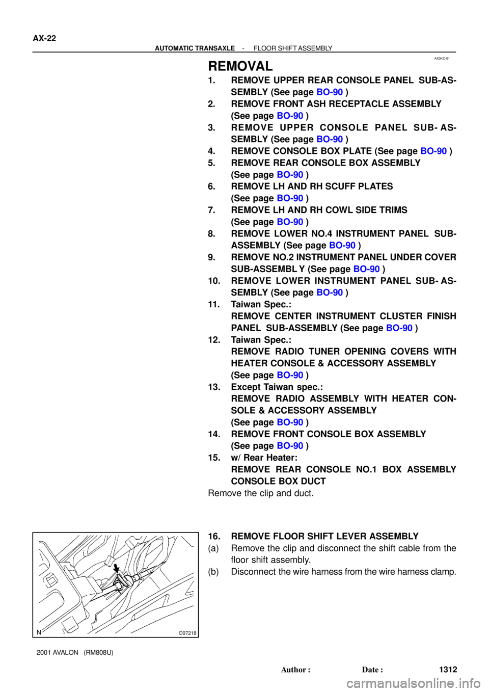
16. REMOVE FLOOR SHIFT LEVER ASSEMBLY
(a) Remove the clip and disconnect the shift cable from the
floor shift assembly.
(b) Disconnect the wire harness from the wire harness clamp.
Page 120 of 1897
AX0KB-01
D07772
Radio Assembly with Heater Control & Accessory Assembly Except Taiwan Spec.:
Lower Instrument Panel
Sub-assembly
Lower No. 4 Instrument
Panel Sub-assembly
Hood Lock
Release Lever
Radio Tuner Opening
Covers with Heater
Console & Accessory
Assembly Taiwan Spec.:Taiwan Spec.:
Center Instrument Cluster Finish Panel
Sub-assemblyNo. 2 Instrument Panel
Under Cover Sub-assembly
Front Ash Receptacle Assembly
Upper Console Panel
Sub-assembly
Console Box Plate
Front Console Box
Assembly
Upper Rear Console
Panel Sub-assembly
Clip
Shift Control
Cable
Floor Shift Lever Assembly
12 (120,9)
Rear Console Box Assembly
RH Cowl Side Trim
RH Scuff Plate
N´m (kgf´cm, ft´lbf) : Specified torqueRH Cowl Side Trim
RH Scuff Plate
AX-20
- AUTOMATIC TRANSAXLEFLOOR SHIFT ASSEMBLY
1310 Author�: Date�:
2001 AVALON (RM808U)
FLOOR SHIFT ASSEMBLY
COMPONENTS
Page 131 of 1897

AX0KC-01
D07218
AX-22
- AUTOMATIC TRANSAXLEFLOOR SHIFT ASSEMBLY
1312 Author�: Date�:
2001 AVALON (RM808U)
REMOVAL
1. REMOVE UPPER REAR CONSOLE PANEL SUB-AS-
SEMBLY (See page BO-90)
2. REMOVE FRONT ASH RECEPTACLE ASSEMBLY
(See page BO-90)
3. REMOVE UPPER CONSOLE PANEL SUB- AS-
SEMBLY (See page BO-90)
4. REMOVE CONSOLE BOX PLATE (See page BO-90)
5. REMOVE REAR CONSOLE BOX ASSEMBLY
(See page BO-90)
6. REMOVE LH AND RH SCUFF PLATES
(See page BO-90)
7. REMOVE LH AND RH COWL SIDE TRIMS
(See page BO-90)
8. REMOVE LOWER NO.4 INSTRUMENT PANEL SUB-
ASSEMBLY (See page BO-90)
9. REMOVE NO.2 INSTRUMENT PANEL UNDER COVER
SUB-ASSEMBL Y (See page BO-90)
10. REMOVE LOWER INSTRUMENT PANEL SUB- AS-
SEMBLY (See page BO-90)
11. Taiwan Spec.:
REMOVE CENTER INSTRUMENT CLUSTER FINISH
PANEL SUB-ASSEMBLY (See page BO-90)
12. Taiwan Spec.:
REMOVE RADIO TUNER OPENING COVERS WITH
HEATER CONSOLE & ACCESSORY ASSEMBLY
(See page BO-90)
13. Except Taiwan spec.:
REMOVE RADIO ASSEMBLY WITH HEATER CON-
SOLE & ACCESSORY ASSEMBLY
(See page BO-90)
14. REMOVE FRONT CONSOLE BOX ASSEMBLY
(See page BO-90)
15. w/ Rear Heater:
REMOVE REAR CONSOLE NO.1 BOX ASSEMBLY
CONSOLE BOX DUCT
Remove the clip and duct.
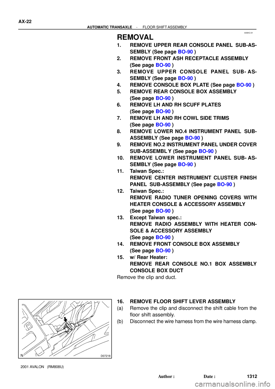
16. REMOVE FLOOR SHIFT LEVER ASSEMBLY
(a) Remove the clip and disconnect the shift cable from the
floor shift assembly.
(b) Disconnect the wire harness from the wire harness clamp.
Page 197 of 1897

C
No.Wire Connector Side
1
2
3
4
6
7
8
9
10
11
12
13
14
15
16ECU-IG No. 2 Fuse
Injector *
1
F (Panel) Fuse
Outside temperature sensor
ECM *
1
ABS ECU
Fuel sender gauge
Fuel sender gauge
Light control volume
RAD No. 1 Fuse Ground
ECU-ACC Fuse
-
Engine coolant temperature sendoer gauge
EFI
Heater control ECU *
117
18
19
20
21Speed control unit
Fuel sender gauge
-
Sender ground
Ground 22Starter Relay
D1
2
3
4
6
7
8
9
10
11
12
13
14
15
16-
Combination meter
-
-
-
- 17
18 -Low oil pressure warning switch *
2
Compressor lock sensor *2
A/C magnet switch
Evaporator temperature sensor *
2
A/C switch *2
A/C indicator *2
-
*1: Hi GradeECM
*2: Lo Grade 5
5Combination meter
Combination meter
Combination meter
Combination meter
Combination meter Combination meter
Combination meter
Combination meter
Combination meter
Combination meter
Combination meter
E
No.Wire Connector Side
1
2
3
4
6
7
8
9
10
11
12
13
14
15
16
17
18
19
205 1
2Compass sensor *1
Compass sensor *1
Compass sensor *1
-
-
-
-
-
-
-
-
-
- Compass sensor *
1
7
Compass sensor *1
- BODY ELECTRICALCOMBINATION METER
BE-47
1651 Author�: Date�:
2001 AVALON (RM808U)
Page 218 of 1897

I12825
34 4017 18
BE0IG-03
I12826
34
17 18
40
ON
ON
W/ Mirror Heater:
W/O Mirror Heater:
I057411
2 34
4 321
I13308
3
6
I13307
5
10
- BODY ELECTRICALDEFOGGER SYSTEM
BE-67
1671 Author�: Date�:
2001 AVALON (RM808U)
INSPECTION
1. A/C control panel assembly:
INSPECT DEFOGGER SWITCH OPERATION
(a) Connect the positive (+) lead from the battery to terminal
17, 18 and negative (-) lead to terminal 40.
(b) Connect the positive (+) lead from the battery to terminal
24 through a 1.4 W test bulb.
(c) Turn the defogger switch ON and check that the test bulb
and indicator light turn ON, then turn OFF after about 15
minutes.
If operation is not as specified, proceed to the next inspection.
2. INSPECT DEFOGGER RELAY CONTINUITY
ConditionTester connectionSpecified condition
Constant3 - 4Continuity
Apply B+ between
terminals 3 and 4.1 - 2Continuity
If continuity is not as specified, replace the relay.
3. W/ Mirror defogger:
INSPECT MIRROR DEFOGGER OPERATION
(a) Connect the positive (+) lead from the battery to terminal
3 and the negative (-) lead to terminal 6.
(b) Check that the mirror becomes warm.
HINT:
It will take a short time for the mirror to become warm.
If the mirror does not become warm, replace the mirror assem-
bly.
4. W/ Mirror defogger and driving position memory:
INSPECT MIRROR DEFOGGER OPERATION
(a) Connect the positive (+) lead from the battery to terminal
5 and the negative (-) lead to terminal 10.
(b) Check that the mirror becomes warm.
HINT:
It will take a short time for the mirror to become warm.
If the mirror does not become warm, replace the mirror assem-
bly.
Page 221 of 1897
BE0IF-03
I12533
Ignition Switch
Driver Side Junction Block
� Defogger Relay
� DEF Fuse
� MIR HTR Fuse
Defogger Wire
Mirror Defogger
Heater Control Assembly
� Defogger Switch
BE-66
- BODY ELECTRICALDEFOGGER SYSTEM
1670 Author�: Date�:
2001 AVALON (RM808U)
DEFOGGER SYSTEM
LOCATION