Page 70 of 1897

AC-85
2007 Author�: Date�:
2001 AVALON (RM808U)
10. INSPECT DIMMING OPERATION
(a) Conn")
I12979
10 8
1
I12977
I12980
10 8
4
I12981
10 8
41
I12982
- AIR CONDITIONINGHEATER CONTROL ASSEMBLY (Manual A/C)
AC-85
2007 Author�: Date�:
2001 AVALON (RM808U)
10. INSPECT DIMMING OPERATION
(a) Connect the positive (+) lead from the battery to terminal
10 and the negative (-) lead to terminal 8 while press the
switch.
(b) Connect the positive (+) lead from the battery to terminal
1 and then check that the indicator dims.
If operation is not as specified, replace the switch circuit board.
11. INSPECT FRESH SWITCH CONTINUITY
Condition / CircuitTester connectionSpecified condition
OFF17 - 8No continuity
ON17 - 8Continuity
If operation is not as specified, replace the switch circuit board.
12. INSPECT REAR DEFOGGER INDICATOR OPERA-
TION
(a) Connect the positive (+) lead from the battery to terminal
10, 4 and negative (-) lead to terminal 8.
(b) Push the RDEF button in and then check that the indicator
lights up.
If operation is not as specified, replace the switch circuit board.
13. INSPECT DIMMING OPERATION
(a) Connect the positive (+) lead from the battery to terminal
10, 4 and negative (-) lead to terminal 8 while press the
switch.
(b) Connect the positive (+) lead from the battery to terminal
1 and then check that the indicator dims.
If operation is not as specified, replace the switch circuit board.
14. INSPECT REAR DEFOGGER SWITCH CONTINUITY
Condition / CircuitTester connectionSpecified condition
OFF4 - 8No continuity
ON4 - 8Continuity
If operation is not as specified, replace the switch circuit board.
Page 71 of 1897
I12937
LO
M1
M2
HI
I12983
AC-86
- AIR CONDITIONINGHEATER CONTROL ASSEMBLY (Manual A/C)
2008 Author�: Date�:
2001 AVALON (RM808U)
15. INSPECT BLOWER SPEED CONTROL SWITCH CON-
TINUITY
Condition / CircuitTester connectionSpecified condition
OFF-No continuity
LO1 - 8Continuity
M11 - 6 - 8Continuity
M21 - 5 - 8Continuity
HI1 - 4 - 8Continuity
If operation is not as specified, replace the switch.
16. INSPECT MODE CONTROL SWITCH CONTINUITY
Condition / CircuitTester connectionSpecified condition
FACE12 - 8Continuity
B/L13 - 8Continuity
FOOT14 - 8Continuity
FOOT/DEF.15 - 8Continuity
DEF.16 - 8Continuity
If operation is not as specified, replace the switch.
Page 72 of 1897
AC2GR-01
I12923
I12922
I12924
Air Mix Control Cable
Air Mix Control
Cable
- AIR CONDITIONINGHEATER CONTROL ASSEMBLY (Manual A/C)
AC-87
2009 Author�: Date�:
2001 AVALON (RM808U)
INSTALLATION
1. INSTALL HEATER CONTROL ASSEMBLY
(a) Install the heater control assembly and stereo opening
cover assembly to 2 brackets.
(b) Install the 8 bolts and 4 screws.
(c) Connect the connectors.
(d) Install the heater control assembly with the 4 bolts.
(e) Pass the through the air mix control cable (Driver side) as
shown the illustration.
Driver side cable should be set between driver side brace
and A/C unit.
(f) Pass the throught the air mix control cable (Passenger
side) as shown the illustration.
Passenger side cable should be set outerside passenger
side side brace.
2. CONNECT HEATER CONTROL CABLES
(a) Set the air mix control knobs to ºMAX. COOLº position.
Page 73 of 1897
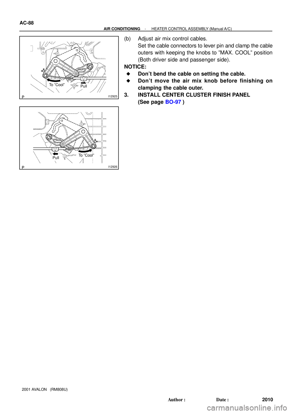
I12925
To ºCoolºPull
I12926
To ºCoolºPull
AC-88
- AIR CONDITIONINGHEATER CONTROL ASSEMBLY (Manual A/C)
2010 Author�: Date�:
2001 AVALON (RM808U)
(b) Adjust air mix control cables.
Set the cable connectors to lever pin and clamp the cable
outers with keeping the knobs to ºMAX. COOLº position
(Both driver side and passenger side).
NOTICE:
�Don't bend the cable on setting the cable.
�Don't move the air mix knob before finishing on
clamping the cable outer.
3. INSTALL CENTER CLUSTER FINISH PANEL
(See page BO-97)
Page 74 of 1897
I12920
AC2GN-01
AC-80
- AIR CONDITIONINGHEATER CONTROL ASSEMBLY (Manual A/C)
2002 Author�: Date�:
2001 AVALON (RM808U)
HEATER CONTROL ASSEMBLY
(Manual A/C)
ON-VEHICLE INSPECTION
INSPECT HEATER CONTROL DIALS OPERATION
Turn the control dials left and right then check that click sound
can be heard and recoil is felt.
If click sound can not be heard or recoil is felt, adjust the control
cable or check control cable and heater control assembly.
Page 75 of 1897
AC2GP-01
I12921
Air Mix Control
CableAir Mix Control
Cable
I12922
I12923
AC-82
- AIR CONDITIONINGHEATER CONTROL ASSEMBLY (Manual A/C)
2004 Author�: Date�:
2001 AVALON (RM808U)
REMOVAL
1. REMOVE CENTER CLUSTER FINISH PANEL
(See page BO-90)
2. DISCONNECT HEATER CONTROL CABLES
NOTICE:
When the air mix damper control cable is disconnected,
should not bend the cable.
3. REMOVE HEATER CONTROL ASSEMBLY
(a) Remove the 4 bolts and pull out the heater control assem-
bly with stereo opening cover assembly, then disconnect
the connectors.
(b) Remove the 8 bolts, 4 screws and 2 brackets.
(c) Separate the heater control assembly and stereo open-
ing cover assembly.
Page 76 of 1897
I12918
Heater Main
RelayAC20T-02
Z19533
34 5
12123 4 5 AC-68
- AIR CONDITIONINGHEATER MAIN RELAY
1990 Author�: Date�:
2001 AVALON (RM808U)
HEATER MAIN RELAY
INSPECTION
1. REMOVE HEATER MAIN RELAY FROM NO. 2 J/B
2. INSPECT HEATER MAIN RELAY
(Marking: HTR) CONTINUITY
ConditionTester connectionSpecified condition
Constant2 - 4
3 - 5Continuity
Apply B+ between
terminals 3 and 5.1 - 2Continuity
If continuity is not as specified, replace the relay.
Page 91 of 1897

AC-15
1937 Author�: Date�:
2001 AVALON (RM808U)
TROUBLESHOOTING (Manual A/C)
PROBLEM SYMPTOMS TABLE
Use the table below to help you find the c")
AC2FV-01
- AIR CONDITIONINGTROUBLESHOOTING (Manual A/C)
AC-15
1937 Author�: Date�:
2001 AVALON (RM808U)
TROUBLESHOOTING (Manual A/C)
PROBLEM SYMPTOMS TABLE
Use the table below to help you find the cause of the problem. The numbers indicate the priority of the likely
cause of the problem. Check each part in order If necessary , replace these parts.
SymptomSuspect AreaSee page
No blower operation
2. HTR Fuse
3. Heater main relay
4. Blower motor
5. Blower resistor
6. Blower speed control switch
7. Wire harness-
AC-68
AC-56
AC-57
AC-83
-
No blower control
1. Blower motor
2. Blower resistor
3. Blower speed control switch
4. Wire harnessAC-56
AC-57
AC-83
-
No air temperature control1. Engine coolant volume
2. Heater control assembly-
AC-80
No compressor operation
1. Refrigerant volume
2. A.C Fuse
3. Magnetic clutch
4. Compressor lock sensor
5. Compressor
6. Pressure switch
7. Heater main relay
8. Blower speed control switch
9. A/C switch
10.A/C amplifier
11. Evaporator temp. sensor
12.Wire harnessAC-3
-
AC-42
AC-42
AC-42
AC-65
AC-68
AC-83
AC-83
AC-77
AC-64
-
No cool air comes out
1. Refrigerant volume
2. Refrigerant pressure
3. Drive belt
4. Magnetic clutch
5. Compressor lock sensor
6. Pressure switch
7. Evaporator temp. sensor
8. A/C switch
9. A/C amplifier
10.Heater control assembly
11. Wire harnessAC-3
AC-3
AC-17
AC-42
AC-42
AC-65
AC-64
AC-83
AC-77
AC-80
-
No engine idle-up when A/C switch ON
1. A/C amplifier
2. Idle control system
3. Wire harnessAC-77
DI-102
-
No air inlet control
1. Air inlet servomotor
2. Heater control assembly
3. Wire harnessAC-39
AC-80
-
No mode control
1. Air outlet servomotor
2. Heater control assembly
3. Wire harnessAC-60
AC-80
-