F09930
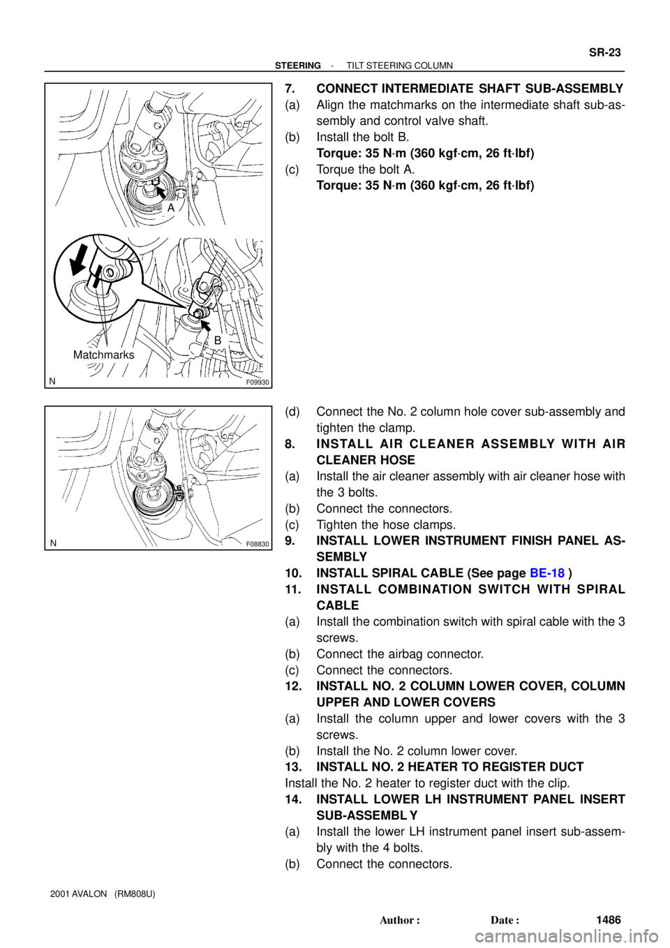
Matchmarks
B
A
F08830
- STEERINGTILT STEERING COLUMN
SR-23
1486 Author�: Date�:
2001 AVALON (RM808U)
7. CONNECT INTERMEDIATE SHAFT SUB-ASSEMBLY
(a) Align the matchmarks on the intermediate shaft sub-as-
sembly and control valve shaft.
(b) Install the bolt B.
Torque: 35 N´m (360 kgf´cm, 26 ft´lbf)
(c) Torque the bolt A.
Torque: 35 N´m (360 kgf´cm, 26 ft´lbf)
(d) Connect the No. 2 column hole cover sub-assembly and
tighten the clamp.
8. INSTALL AIR CLEANER ASSEMBLY WITH AIR
CLEANER HOSE
(a) Install the air cleaner assembly with air cleaner hose with
the 3 bolts.
(b) Connect the connectors.
(c) Tighten the hose clamps.
9. INSTALL LOWER INSTRUMENT FINISH PANEL AS-
SEMBLY
10. INSTALL SPIRAL CABLE (See page BE-18)
11. INSTALL COMBINATION SWITCH WITH SPIRAL
CABLE
(a) Install the combination switch with spiral cable with the 3
screws.
(b) Connect the airbag connector.
(c) Connect the connectors.
12. INSTALL NO. 2 COLUMN LOWER COVER, COLUMN
UPPER AND LOWER COVERS
(a) Install the column upper and lower covers with the 3
screws.
(b) Install the No. 2 column lower cover.
13. INSTALL NO. 2 HEATER TO REGISTER DUCT
Install the No. 2 heater to register duct with the clip.
14. INSTALL LOWER LH INSTRUMENT PANEL INSERT
SUB-ASSEMBL Y
(a) Install the lower LH instrument panel insert sub-assem-
bly with the 4 bolts.
(b) Connect the connectors.
F08830
- STEERINGTILT STEERING COLUMN
SR-13
1476 Author�: Date�:
2001 AVALON (RM808U)
3. REMOVE LOWER NO. 1 INSTRUMENT PANEL SUB-
ASSEMBLY
(a) Remove the 2 screws and disconnect the hood lock re-
lease lever.
(b) Remove the 2 screws.
(c) Disconnect the connectors and remove the lower No. 1
instrument panel sub-assembly.
4. REMOVE LOWER LH INSTRUMENT PANEL INSERT
SUB-ASSEMBL Y
(a) Disconnect the connectors.
(b) Remove the 4 bolts and lower LH instrument panel insert
sub-assembly .
5. REMOVE NO. 2 HEATER TO REGISTER DUCT
Remove the clip and No. 2 heater to register duct.
6. REMOVE NO. 2 COLUMN LOWER COVER, COLUMN
UPPER AND LOWER COVERS
(a) Remove the No. 2 column lower cover.
(b) Remove the 3 screws, column upper and lower covers.
7. REMOVE COMBINATION SWITCH WITH SPIRAL
CABLE
(a) Disconnect the connectors.
(b) Disconnect the airbag connector.
(c) Remove the 3 screws and combination switch with spiral
cable.
8. REMOVE SPIRAL CABLE (See page BE-18)
NOTICE:
Do not disassemble the spiral cable or apply oil to it.
9. REMOVE LOWER INSTRUMENT FINISH PANEL AS-
SEMBLY
10. REMOVE AIR CLEANER ASSEMBLY WITH AIR
CLEANER HOSE
(a) Loosen the hose clamps.
(b) Disconnect the connectors.
(c) Remove the 3 bolts and air cleaner assembly with air
cleaner hose.
11. DISCONNECT INTERMEDIATE SHAFT SUB- AS-
SEMBLY
(a) Loosen the clamp and disconnect the No. 2 column hole
cover sub-assembly.